AMETEK DCS-E 1kW Series Programming Manual User Manual
Page 25
DLM-E Series and DCS-E Series
Isolated Analog Programmer Operation
2.3.7
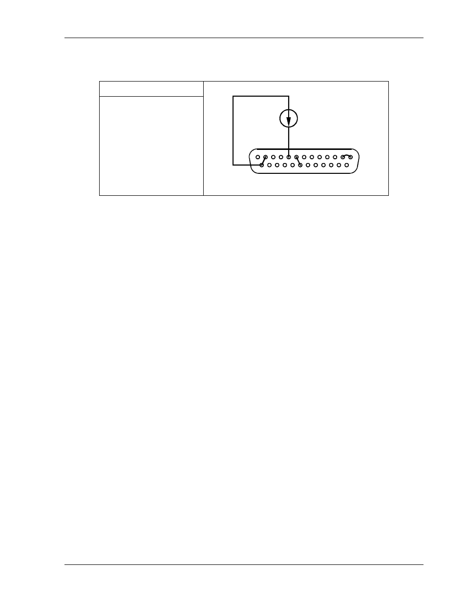
4-20mA Current Source Programming of Output Voltage
SW1 Switch Settings
SW1-1 ON (1) = 4-20mA
8
4-20mA
9
12
13
1
2
25
14
20
Set up for 4-20 mA programming of the output voltage as follows:
1.
Set SW1-1, V PROG, to ON (1) for 4-20mA programming range.
2.
Connect the external programming current source to the ISOLATED ANALOG
PROGRAMMER connector, J4, with the source to Pin-9 and the return to Pin-25.
3.
Connect a jumper from Pin-25 to Pin-12 to connect the 4-20mA current sense resistors
to common.
4.
Connect a jumper from Pin 20 to Pin 8 to provide the negative 2.5VDC to zero out the
4mA signal generated by internal circuits.
5.
Connect Pin-1, ANALOG-CONTROL, of the ISOLATED ANALOG PROGRAMMER
connector, J4, to Pin-2 to enable remote control.
6.
Program the other parameters to the desired limit values.
M51A Option
2-13