Section 2 isolated analog programmer operation, 1 sw1 switch, Isolated analog programmer operation – AMETEK DCS-E 1kW Series Programming Manual User Manual
Page 13
SECTION 2
ISOLATED ANALOG
PROGRAMMER OPERATION
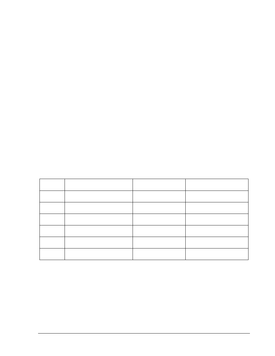
2.1 SW1 Switch
The SW1 SETUP switch is accessible from the rear panel of the unit. It provides user selection
of the programming/monitoring ranges and shutdown logic signal level. Setting a switch to the 1
or 0 position changes a range. The factory default settings are shown below.
Refer to Figure 2–1 for a rear panel view of the DLM-E 3kW and 4kW models.
Refer to Figure 2–2 for a rear panel view of the DCS-E 1kW models.
Switch
Position
Function
OFF (0) Position
ON (1) Position
1
Voltage Programming
Range Select
0-10 VDC
* 0-5 VDC, 4-20mA
2
Current Programming
Range Select
0-10 VDC
* 0-5 VDC, 4-20mA
3
OVP Programming
Range Select
0-10 VDC
* 0-5 VDC
4
Output Voltage Monitor
Range Select
* 0-5 VDC
0-10 VDC
5
Output Current Monitor
Range Select
* 0-5 VDC
0-10 VDC
6
Remote ON-OFF Level
Select
Active Low Signal
* Active High Signal
* Indicates default settings
Table 2–1. SW1 SETUP Switch
M51A Option
2-1