Vectronics VEC-8218K User Manual
Page 12
VEC-8218K Owner’s Manual
Counter-Surveillance Monitor Kit
11
! ! 47.#Connect the lead from CW to the bottom lead of the 10K pot and
solder.
Locate the red (+) lead going from the battery snap connector to SW (+) on the
PC board. Perform the following steps:
! ! 48.#Measure back 2" from the SW (+) end and snip the wire.
! ! 49. Dress both ends, removing 1/4" of insulation and tinning the leads.
Find the two off/on switch terminals on the back of 10K pot R24:
Switch Terminals
Red Leads
! ! 50.#Install the snap-clip end of the red lead to one switch terminal.
! ! 51.#Install the SW (+) red battery lead to the other switch terminal.
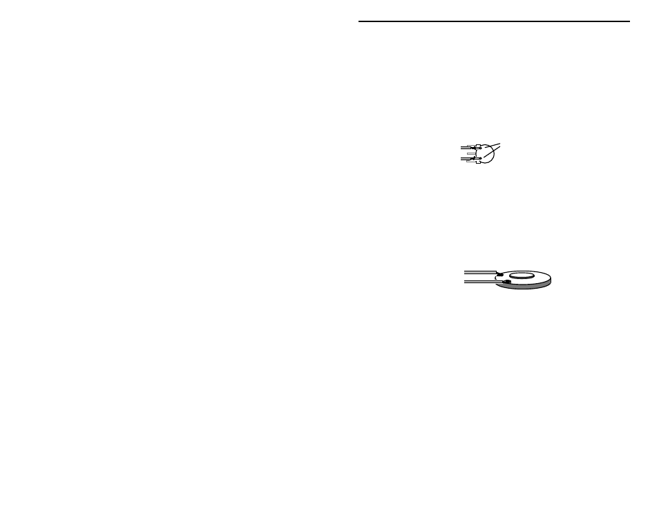
Locate the small 8 ohm speaker supplied with your kit. Also, find two (2) equal
lengths of insulated wire:
Speaker Leads
Speaker
! ! 52.#Solder a lead to each of the two (2) speaker connections on the plastic
frame.
! ! 53.#Install one speaker lead at SPK1 on the PC board (either hole).
! ! 54.#Install the second lead at the other SPK1 hole on the PC board.
Find one last length of hook-up wire. This will be used for connecting the
collapsible whip later on.
! ! 55.#Install one end of the wire at ANT on the PC board.
This concludes wiring of your VEC-8218 Surveillance Monitor Kit. Before
moving on to the next section, give your kit a thorough QC (quality control)
inspection. This will help you discover accidental assembly errors that might
prevent it from working properly--or that might cause damage to sensitive parts
when you apply power. Follow this procedure: