Vectronics VEC-8218K User Manual
Page 10
VEC-8218K Owner’s Manual
Counter-Surveillance Monitor Kit
9
the two.
Locate two (2) 10 uF electrolytic capacitors.
! ! 32.#Install 10 uF at C9 and solder.
! ! 33.#Install 10 uF at C10 and solder.
This completes capacitor installation. Before moving on, check each electrolytic
for correct polarity.
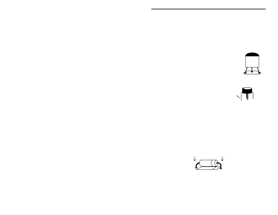
Locate two (2) PN2222 plastic transistors. Like the
electrolytic caps, transistors must be oriented correctly to
work.
! ! 34.#Install a PN2222 at Q2 and solder.
! ! 35.#Install a PN2222 at Q3 and solder.
Locate the MRF 901. This device resembles
a small black plastic pill with four leads. The
longest lead is the collector, also
distinguished by the letter “M”. Carefully
bend each lead down, forming a right-angle to
the component body (make sure the "M" is on
top).
Now, locate the silk-screened footprint for Q1.
! ! 36.#Gently insert all four leads into the board, making sure the collector
lead is positioned correctly. The body should rest flush with the PC
board surface. Turn the board over, keeping an index finger on Q1,
and bend the leads to secure the device in place.
! ! 37.#Solder all four leads of Q1.
Find the 1N270 diode (glass body). Like transistors, diodes are polarized
devices that must be installed correctly. Always look for the banded end when
installing.
! ! 38.#Install the 1N270 diode at D1 and solder.
Find the LM324 IC. The IC is keyed at one end to indicate proper positioning.
During installation, orient the IC so the notch corresponds to the key on the PC
layout.
Collector
MRF901
PN2222