Vectronics VEC-1500K User Manual
Page 63
58
Install a jumper between points W3 and WD. Solder.
Install a jumper between points W7 and WH. Solder.
Install a jumper between points W6 and WG. Solder.
Install a jumper between points W2 and WC. Solder.
Install a jumper between points W0 and WA, Solder.
Install a jumper between points W1 and WB. Solder.
Install a jumper between points W5 and WF. Solder.
Locate the 9-volt battery snap.
Insert the black lead at the point marked “GND” on the parts
placement diagram. This is near capacitor C4. Solder.
The red wire from the battery snap should go the point marked
“+9V” on the parts placement diagram, this is near diode D1.
Solder.
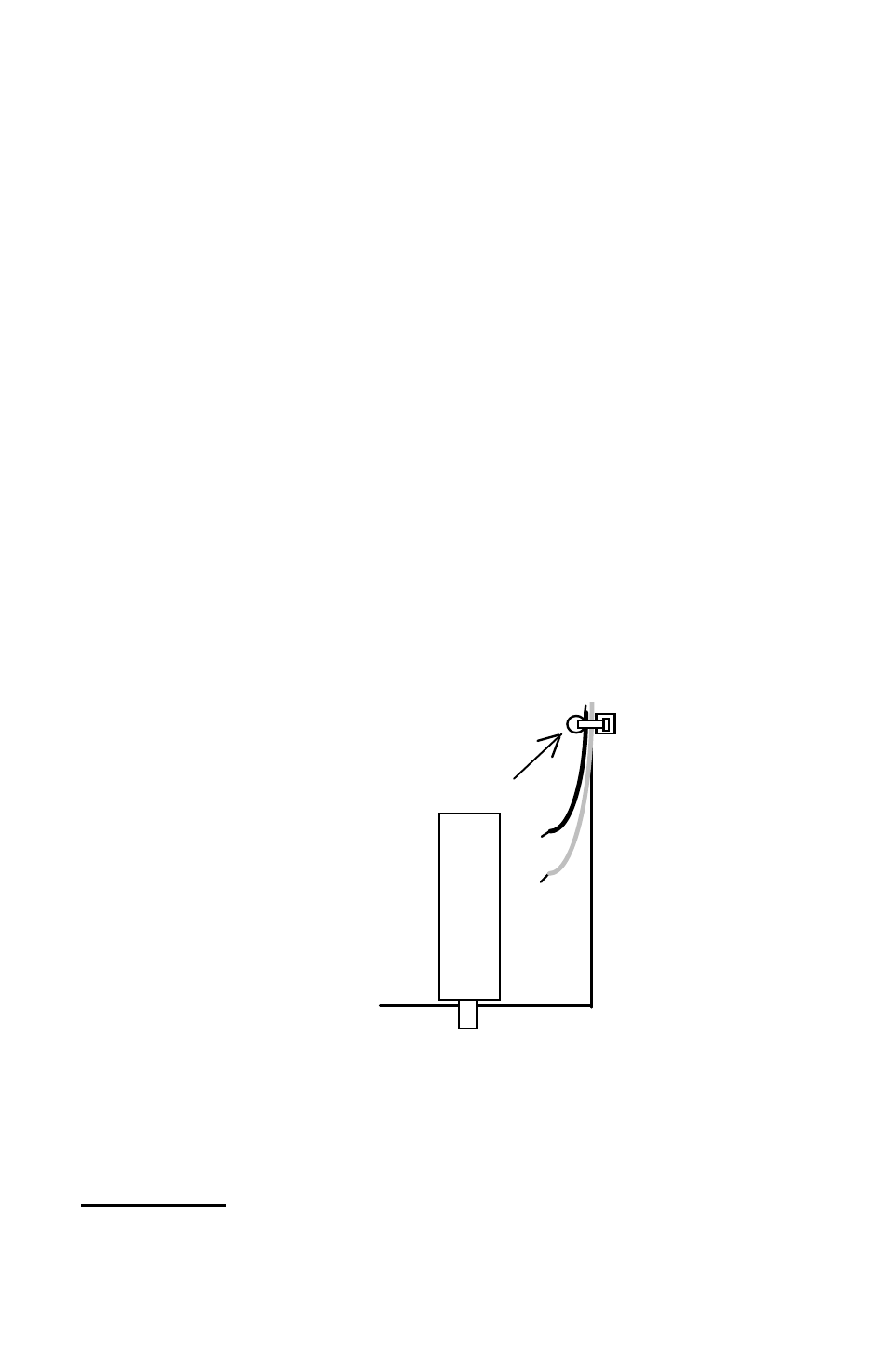
Use a 4” nylon wire tie to secure the battery leads to the PC board.
The wire tie hole is located near Q10.
+ red
- black
Tie wrap
SW1
Locate the NE555 timer IC.
Important Note: An IC body has a small notch, or key, molded at one end, to
indicate pin 1. A small dimple-like body-molding is often found adjacent to pin 1.
Some IC packages may include both key indicators.