Vectronics VEC-1500K User Manual
Page 34
29
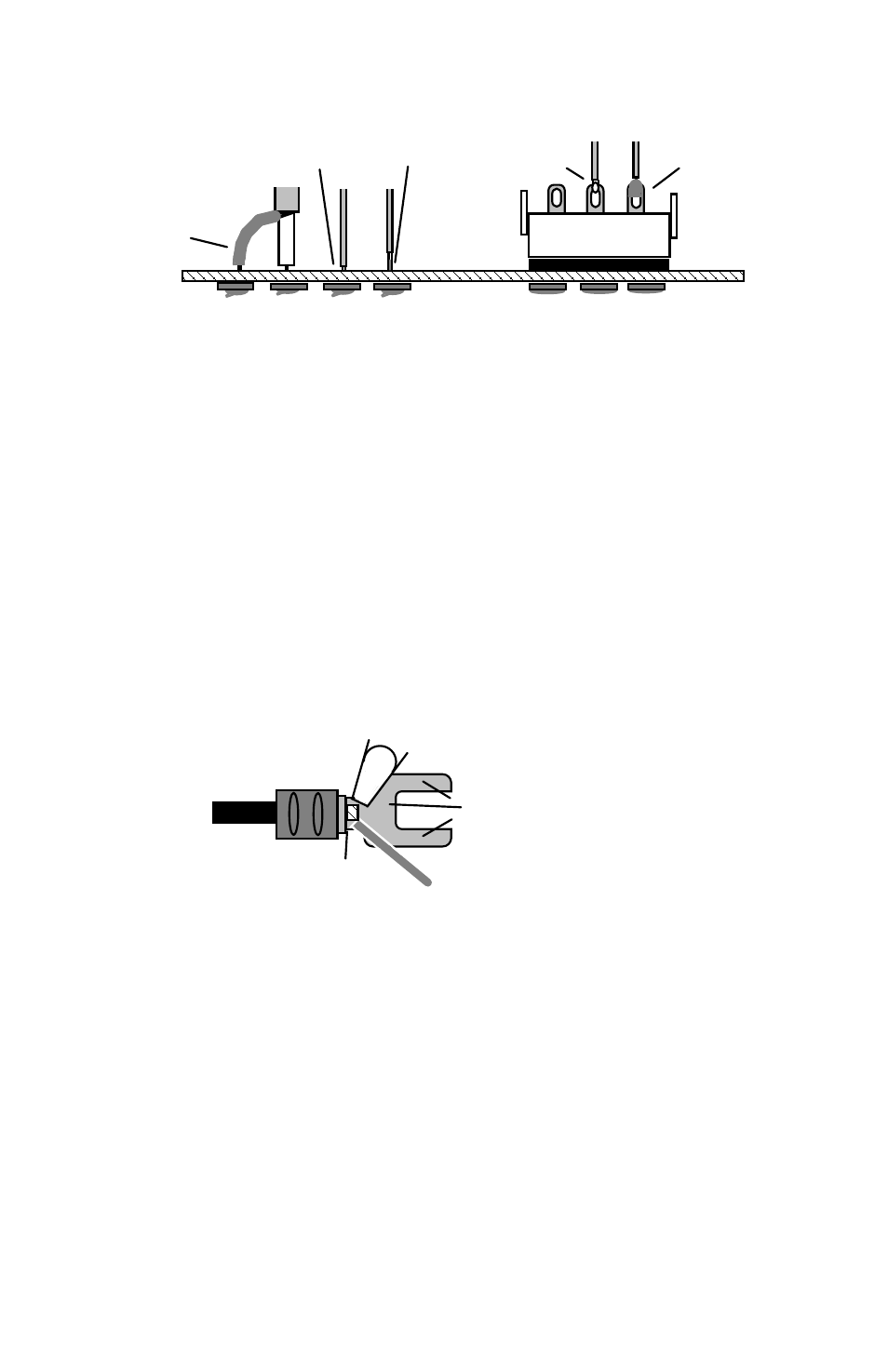
Sleeve
exposed
shields
"wicking"
Wrap wire
around
terminal
Use minimal
solder
Plug
Avoid
Dress
insulation
close
To prevent exposing un-insulated wire, install sleeving on ground shields. Also,
dress wire insulation close to the board surface. When installing wires, avoid
applying excess heat and solder--this causes hot solder to wick up wire strands,
melt the insulation, and destroy wire flexibility (a major cause of breakage). The
same rules apply to plugs. Dress insulation close to terminal tabs, and use
minimal heat to prevent wicking. Follow the plug manufacturer's assembly
instructions for capping plugs and immobilizing wires.
Larger control-system harnesses may use crimp-lugs to interconnect wires on
terminal blocks. If these wires carry high-frequency signals, or if the terminals
are exposed to harsh environmental conditions, crimping and soldering may be
specified. When installing the lugs, crimp the wire (or wires) in place first--then
apply heat, allowing solder to wick back into crimp area. Avoid depositing
solder on the screw-down portion of the lug. This will make tightening to the
block impossible later on!
Solder
Iron Tip
Wick solder
into crimp area
Keep solder clear of
terminal contact area.
Chassis Connectors:
When soldering wires to chassis connectors, observe the
same precautions you would for PC board installation. If the connector terminal
allows the wire end to pass through an opening, wrap it tight for a good
mechanical connection before applying solder. If the wire end inserts into a
hollow connector terminal, tin it prior to insertion for easier installation and
better solder coverage.