Appendix “a – Pinnacle Systems DR User Manual
Page 34
Appendix “A”
Diagnostics & Troubleshooting
Error Conditions
When an ERROR message is displayed, the end of the
message will display a set of numbers to indicate where
along the pylon the problem resides.
The fi rst two numbers displayed represent the fi rst
problem beam on the guard starting from the cable
end of the pylon. The third number represents the total
number of beams blocked on the guard. Boards inside
each pylon are exactly four inches long. Using this you
can determine which board in the pylon is bad.
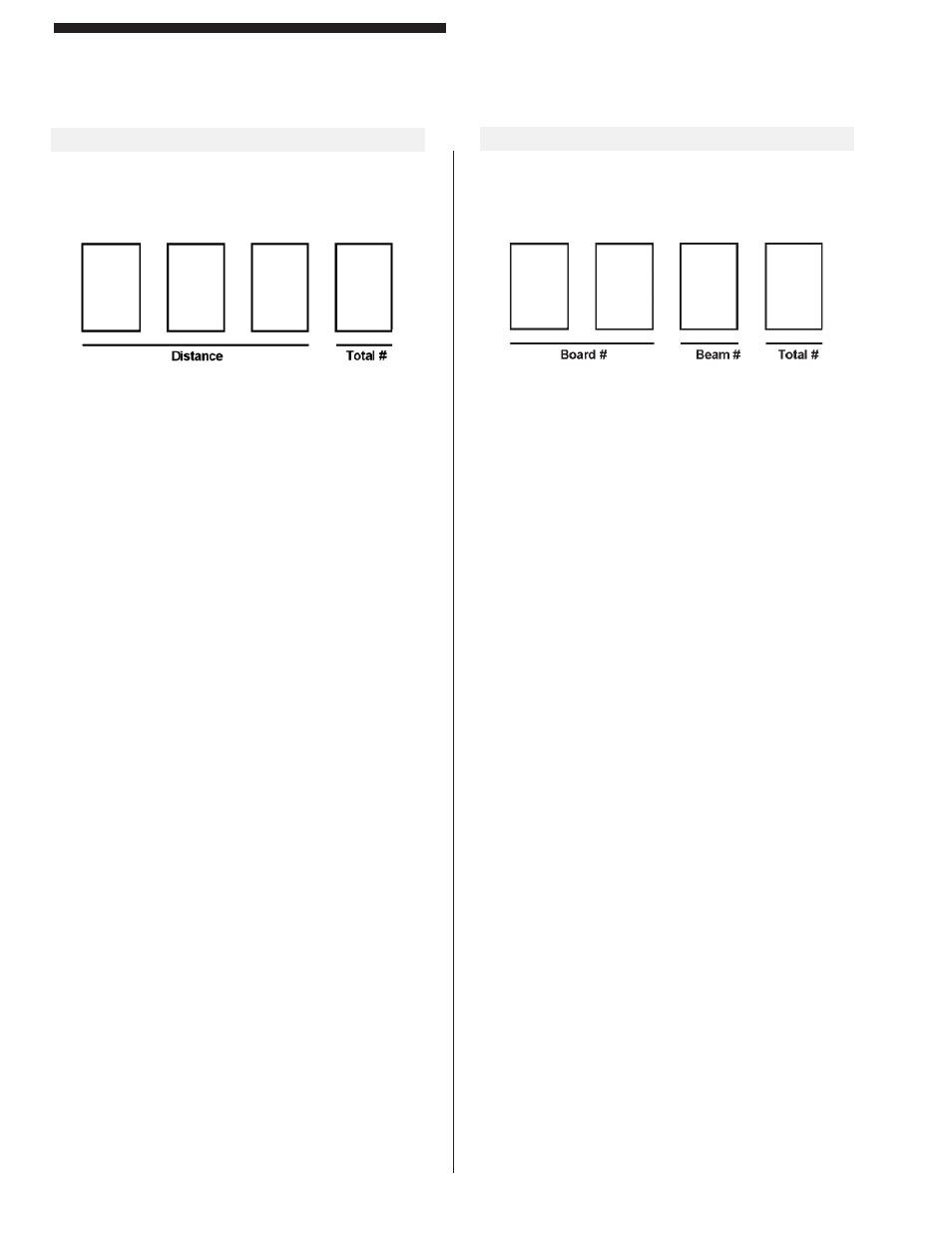
Defi nitions
BOARD #: Indicates fi rst board on which a problem
was detected (01 to 17).
(i.e., 01 = board nearest cable connection)
BEAM #:
Indicates fi rst problem beam on the board
indicated above (1 to 8).
(i.e., 1 = fi rst beam on board, 8 = last beam
on board)
TOTAL #: Indicates total number of blocked beams
on the curtain.
(i.e., 1 to 9 beams then A to F = 10 to 15
beams)
Obstruction or Misalignment
When the curtain is obstructed or misaligned, the
display will present four numbers to indicate location of
obstruction or misalignment.
Distance: The fi rst three numbers displayed represent
(in inches) the fi rst obstructed or misaligned beam on the
guard starting from the cable end of the pylon. The third
digit is blank for whole inches and “5” for half inches.
Total #: The last digit indicates the total number of
beams blocked or misaligned. The digit counts in
Hexadecimal (0 to F = 0 to 15 beams). A “>” sign
indicates more than 15 beams missing.
“A”=10 beams, “B”=11 beams, “C”=12 beams, “D”=13
beams, “E”=14 beams, “F”=15 beams
Computing Object Size: To compute an object’s size,
use the following formula: size(inches) = TOTAL# x 0.5”
This can be used to evaluate an object’s size up to 7.5”
in diameter.
(i.e., TOTAL# = 3 so SIZE = 1.5”)
(i.e., TOTAL# = D so SIZE = 6.5”)
Examples:
1255 = First obstruction located 12.5” from
connector, size of object is 2.5”
05 A
= First obstruction located 5.0” from connector,
size of object is 5.0”
A-1