Standard features – Pinnacle Systems DR User Manual
Page 14
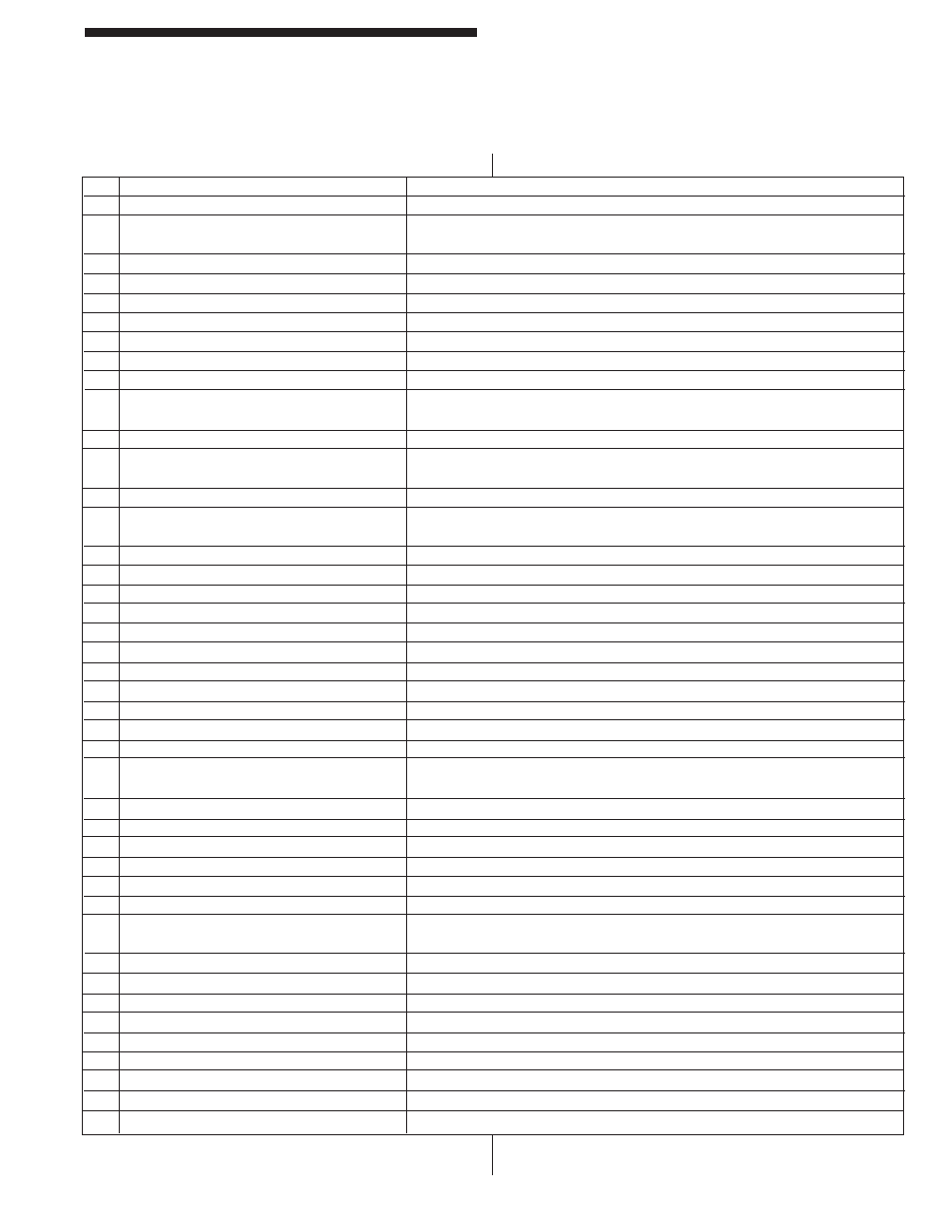
5
Standard Features
DIN-rail Controller Module
Table 1: DIN-rail Serial Port Diagnostics
DIAGNOSTICS
DISPLAY
DESCRIPTION
A
RDY
Ready
(GREEN
light)
B
01 > (numbers on screen show where
Blockage of curtain fi eld (RED) relays are off.
blockage
occurred)
C
SIZE
Auto Blank object size to large.
D
MOVE
Auto
Blank
object
moved.
E
PENT
Curtain penetrated and locked out (RED)
F
Waiting for reset button to be pushed (scrolling or error code).
G
Reset
button
has
been
pushed.
H
CINN
Cincinnati
Interface
active
(+24v).
I
MUTE
Mute Out in active muting state (outputs bypassed).
J
Emitter turned off (occurs after you remove blockage to check for external
infrared
sources).
K
Blockage
of
curtain
fi eld but waiting for relays to turn off.
L
01 > (numbers on screen show where
No blockage, relays off, trying to turn on.
blockage
occurred)
M
CPU responding with last order from another CPU.
U
MUTE-OUT SWITCH FAULT
Signal inputs that control Mute function where either in MUTE at power up or both
high or low (same state for too long).
V
OPEN EMITTER PYLON
LED in pylon failed or cable to pylon off or bad.
W
SHORT IN EMITTER PYLON
LED in pylon shorted.
X
EMITTER LENGTH FAULT
Physical length of pylon does not match settings in box.
Y
RECEIVER LENGTH FAULT
Physical length of pylon does not match settings in box.
Z
EXT RELAY CONTACT WELD / WIRE CUT
External relay input signal open all the time or at the wrong time.
[
EXT RELAY CONTACT SHORTED
External relay input signal short all the time or at the wrong time.
\
INT RELAY CONTACT STUCK ON
Internal relay closed, but should be open.
]
INT RELAY CONTACT STUCK OFF
Internal relay open but should be closed.
^
NO DATA LINE DETECTED
Slave could not detect data line from Master
_
NO CLOCK LINE DETECTED
Slave could not detect clock line from Master
‘
No G LINE DETECTED
Slave could not detect G line from Master
a
EXT INFRARED SOURCE DETECTED
Receiver pylon indicating seeing signals when none were transmitted by Emitter
pylon.
b
RELAY BAD OR MISSING
No RED or GREEN light on box lit up.
c
RAM FAILURE
Ram would not clear.
d
HAD POWER ON RESET
Slave processor has reset itself.
e
HAD CLOCK/WATCHDOG FAILURE
Oscillator or Watchdog failure.
f
DATA TRANSFER CORRUPTED
Checksum error between Master and Slave CPU’s.
g
SERIAL TRANSFER INCOMPLETE
Slave and Master could not talk to each other.
h
DATA FROM RECEIVER PYLON NOT
Data coming from Receiver pylon not correct.
CORRECT
i
EMITTER ON AT WRONG TIME
LED in Emitter pylon was on but not supposed to be.
j
RECEIVER IS OSCILLATING
A phototransistor in the Receiver pylon was Oscillating.
k
NO MORE CODES
Displayed after all stored fault codes are displayed.
l
INITIATE EEPROM
New EEPROM was tested and initialized for initial use
m
Master wants Slave to store new AB data
n
AB DATA CORRUPTED
Stored Auto Blank pattern has been corrupted.
o
RESET BUTTON HELD DOWN TOO LONG
Reset button has been held down too long or is broken.
p
NO ACK FROM EEPROM
Cannot talk to EEPROM memory.
q
ESTP
Emergency
Stop
Input
4
Standard Features
DIN-rail Controller Module