Installation procedures, Controller module setup – Pinnacle Systems DR User Manual
Page 26
19
Installation Procedures
DIN-rail Controller Module
Controller Module Setup
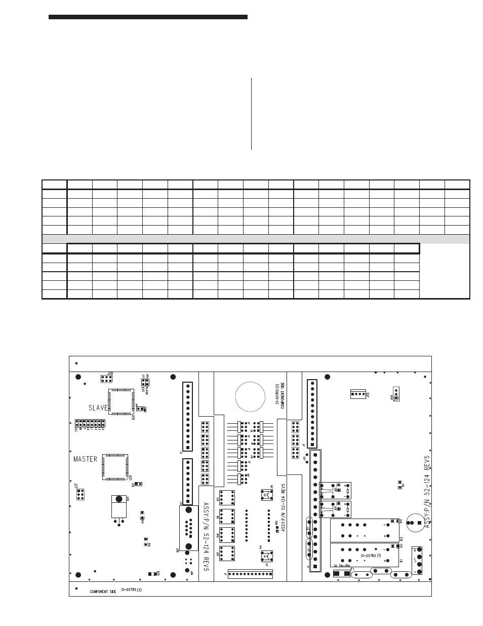
Internal jumpers inside the Controller Module allow for
selection of pylon length (height of tower itself). Table
6 demonstrates how to set the internal jumpers if you
wish to use the Controller Module with a set of pylons
that are a different length.
EXT
Activates External Relay Checking function
(see Standard Features, “External Relay
Check”).
FLASH
Increases immunity to weld fl ash by slowing
down the curtain (doubles response time).
CLOSE Activates Latching Relay Reset feature (see
Standard Features, “Resettable Latching
Relays”).
AB/FLT Selects either Auto Blank or Floating Blank
(jumper = Auto Blank).
Figure 4: Internal Circuit Board View
Table 6: Internal Jumper Settings with Different Pylon Lengths
16
Installation Procedures
DIN-rail Controller Module
4"
8"
12"
16"
20"
24"
28"
32"
36"
40"
44"
48"
52"
56"
60"
64"
L0
1
1
1
1
1
1
1
1
L1
1
1
1
1
1
1
1
1
L2
1
1
1
1
1
1
1
1
L3
1
1
1
1
1
1
1
1
L4
1
1
1
1
1
1
1
1
1
1
1
1
1
1
1
1
68"
72"
76"
80"
84"
88"
92"
96"
100"
104"
108"
112"
116"
120"
L0
1
1
1
1
1
1
1
L1
1
1
1
1
1
1
1
1
L2
1
1
1
1
1
1
1
1
L3
1
1
1
1
1
1
1
1
L4
1 = Jumper
For pylons with 1” beam spacing, install the Jumper plug (just below L0)
For pylons with 1/2” beam spacing, remove the Jumper plug (just below L0)