Installation procedures – Pinnacle Systems DR User Manual
Page 23
16
Installation Procedures
DIN-rail Controller Module
RS-232 Serial Port (optional)
Terminal Connector
1 +15VDC
out
2 Transmit
3 Receive
5 Ground
6 +15VDC
Out
8 +15VDC
out
9 Ground
Wiring
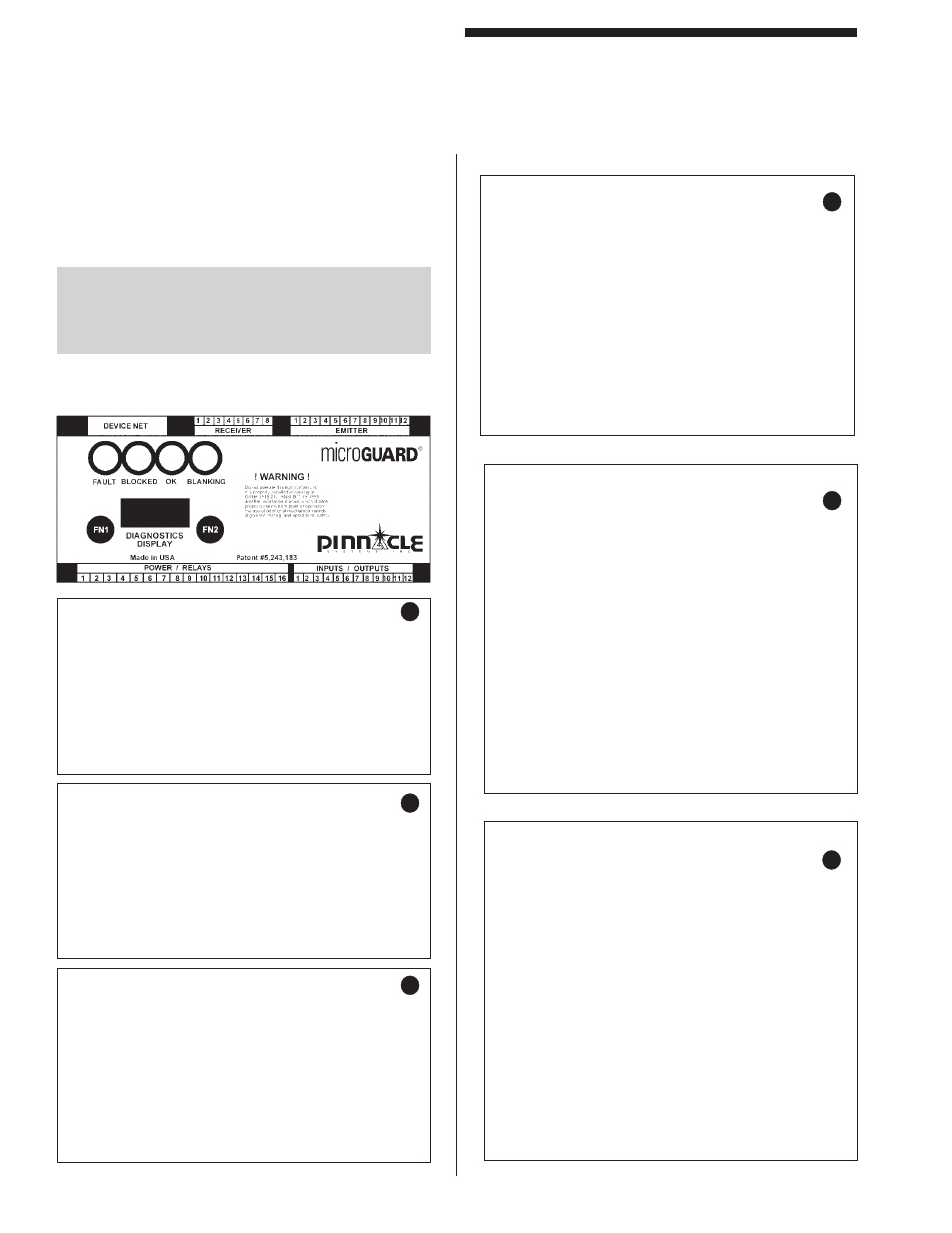
Table 5 is a sample of how to wire the Controller Module.
Certain features are not needed for many installations.
Read the sections in this manual describing each feature
to decide which feature(s) you may need.
WARNING: Both K1 and K2 Safety Output Relays
must be used to issue a “STOP” signal to your
hazardous machinery—either with two separate stop
circuits or both relays wired in series.
RS-485 Serial Port (optional)
Terminal Connector
1 +15VDC
out
2 tx/rx
3 tx/rx
5 Ground
6 +15VDC
Out
8 +15VDC
out
9 Ground
Tables 5a-f: Controller Module Wiring
b
c
a
Receiver Wire Colors
Terminal Connector
1
Green & Red
2
Black & Brown
3 Purple
4 White
5 Blue
6 Yellow
7 Orange
8 Shield
(bare)
Inputs / Outputs
Terminal Connector
1
Analog Output + side
2
Analog Output - side
3
Latching Relay Input (ground to reset)
4
Mute-Out Input (LS4 input)
5
Mute-Out (LS5 input)
6
Remote Key Switch Key #1 (black wire)
7
Remote Key Switch Key #2 (red wire)
8
ESTOP Button 2
9
+24VDC input to power optically coupled
inputs
10
Remote Blanking Indicator Output (ground
when on)
11
Remote Blocked Indicator Output (ground
when on)
12
Remote OK Indicator Output (ground when
on)
Power/Relays
Terminal Connector
1 +24VDC
Input
2
-24 VDC input
3 Earth
Ground
4
Safety Relay K1 N.O. (Red = open)
5
Safety Relay K1 N.O.
6
Safety Relay K2 N.O.
7
Safety Relay K2 N.O.
8
Auxiliary Relay K3 N.O.
9
Auxiliary Relay K3 Common
10
Auxiliary Relay K3 N.O.
11
Fault Relay K4 N.O. (open = fault)
12
Fault Relay K4 N.O.
13
External Relay Input + side
14
External Relay Input - side
15
ESTOP +24VDC (optional CINN +)
16
ESTOP Button 1 (optional CINN-)
d
e
f
Emitter Wire Colors
Terminal Connector
1 Shield
(bare)
2 Yellow
3
Orange & Blue
4 Purple
5 Black/White
6 Brown
7 Green
8 Red
9 Red/white
10 Gray
11 Black
12 White
13
Installation Procedures
DIN-rail Controller Module