One Systems PT-10 User Manual
Page 27
One Systems, Inc. 6204 Gardendale Dr., Nashville, TN 37215
27
This image represents the Link assembly with the enclosure in a vertical orientation and
the Link using the lower eyebolt position
Figure 8b
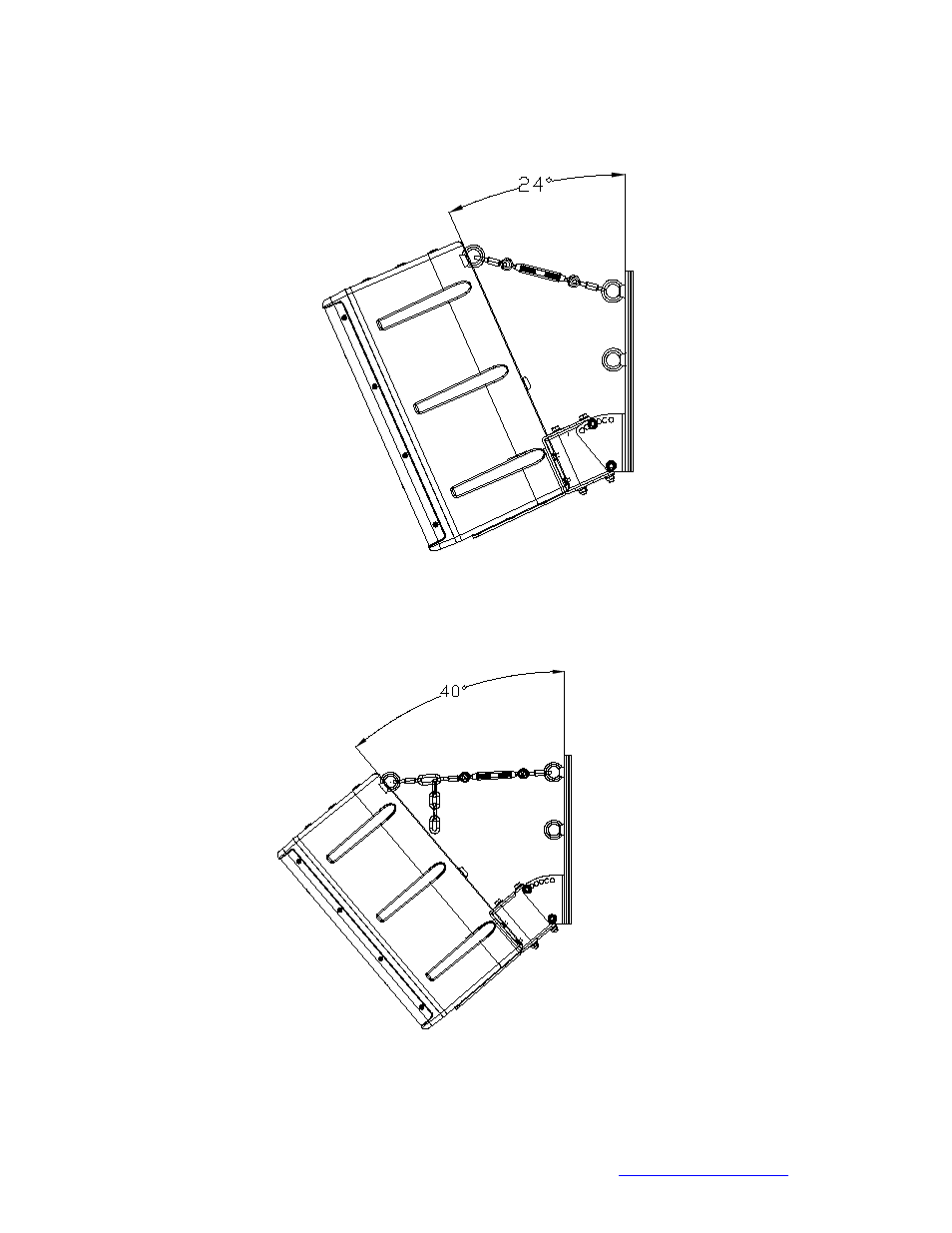
Figure 8b represents the Link with the enclosure in a 24 degree tilt. The Link is using
the top eyebolt and the turnbuckle has been adjusted to provide mild tension.
Figure 8c