NEXCOM VTC 6200 User Manual
Page 47
Copyright © 2011 NEXCOM International Co., Ltd. All rights reserved
34
VTC 6200 / VTC 6200-NI / VTC 6200-NI-DK User Manual
Chapter 2: Jumpers and Connectors
GPS Connector
Connector size: JST 6-pin, 2.54 mm pitch
Connector location: J8
1
6
Pin
Definition
1
GPS_BAT
2
GPS_LED#
3
SP_TX1
4
SP_RX1
5
GND
6
VCC3_3S
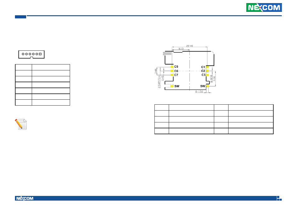
SIM Card Connector
Connector location: CN4
Connector Pin Definition
Pin
Definition
Pin
Definition
C1
POWER VOLTAGE
C2
RESET SIGNAL
C3
CLOCK SIGNAL
C5
GND
C6
VPP:PROGRAM VOLTAGE
C7
I/O
SW
Contact present switch
Note: Please refer to Appendix E for the pin definition information
of GPS with dead reckoning feature.
This manual is related to the following products:
See also other documents in the category NEXCOM Hardware:
- EBC 352 (68 pages)
- EBC 353 (62 pages)
- EBC 355 (63 pages)
- EBC 354 (63 pages)
- ICES 268 (96 pages)
- ICES 667 (100 pages)
- ICES 254 (98 pages)
- NEX 604 (61 pages)
- NEX 608 (67 pages)
- ICES 668 (105 pages)
- NEX 607 (75 pages)
- NEX 609 (61 pages)
- NEX 611 (51 pages)
- NEX 613 (45 pages)
- NEX 617 (53 pages)
- NISE 101 (79 pages)
- NISE 104 (78 pages)
- NISE 2020 (84 pages)
- NISE 105A (78 pages)
- NISE 103 (83 pages)
- NISE 2110A (87 pages)
- NISE 2420 (84 pages)
- NISE 301 (74 pages)
- NISE 2310E (107 pages)
- NISE 2210E (110 pages)
- NISE 3100eP2 (75 pages)
- NISE 300 (95 pages)
- NISE 3140P2E (88 pages)
- NISE 3520P2E (125 pages)
- MAC 3500P2-GTS8 (120 pages)
- NISE 3600E (102 pages)
- NISE 3720P2E (85 pages)
- NISE 3640P2E (105 pages)
- NISE 3640M2E (108 pages)
- NISE 4000 (102 pages)
- nTUF 600 (100 pages)
- NEX 716VL2G (71 pages)
- NISE 4000P4E (128 pages)
- NISE 4000P2E (131 pages)
- NEX 732L2G (71 pages)
- NEX 883 (53 pages)
- NEX 890 (58 pages)
- NEX 980 (52 pages)
- NEX 852VL2 (62 pages)
- NEX 981 (47 pages)