NEXCOM VTC 6200 User Manual
Page 25
Copyright © 2011 NEXCOM International Co., Ltd. All rights reserved
12
VTC 6200 / VTC 6200-NI / VTC 6200-NI-DK User Manual
Chapter 1: Product Introduction
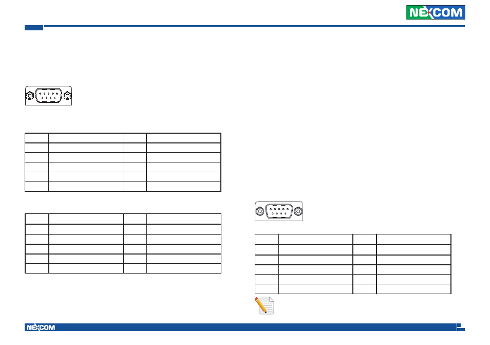
Isolated GPIO Connector
Connector size: DSUB-9 pin
Connector location: COM1
Pin
Description
Pin
Description
1
Isolated GIN1
2
Isolated GIN2
3
Isolated GIN3
4
Isolated GIN4
5
Isolated GOUT4
6
Isolated GND
7
Isolated GOUT3
8
Isolated GOUT2
9
Isolated GOUT1
9
5
1
6
Connector pin definition (VTC 6200-NI, VTC 6200-NI-DK)
PIn
Definition
Pin
Definition
1
GIN1
2
GIN2
3
GIN3
4
GIN4
5
GOUT4
6
GOUT1
7
GOUT2
8
GOUT3
9
GND
10
GND
Connector pin definition (VTC 6200)
VGA Port x2 (Clone Mode)
The DB15 VGA port supports resolutions up to 1600x1200 @ 85 Hz,
2048x1536 @ 60Hz.
USB Port x 2
The two USB ports are compliant with USB 2.0 specifications.
LAN Port
The LAN port is an RJ45 interface with integrated LEDs and supports
10/100/1000Mbps Ethernet data transfer rates.
Audio Jacks (MIC-IN and LINE-OUT)
• MIC-IN jack receives monophonic input from an external microphone.
• LINE-OUT jack is the stereo output for connecting external speakers.
Odometer Sensor Connector (for VTC 6200-NI-DK)
Connector size: DSUB-9 PIN
Connector location
PIn
Definition
Pin
Definition
1
DIR_N
6
GND
2
DIR_P
7
NC
3
NC
8
NC
4
PULSE_P
9
GND
5
PULSE_N
9
1
5
6
Note: Please refer to Appendix E for the pin definition information
of GPS with dead reckoning feature.