KBC Networks WES User Manual
Page 8
WES Mesh Wireless System Operations Manual
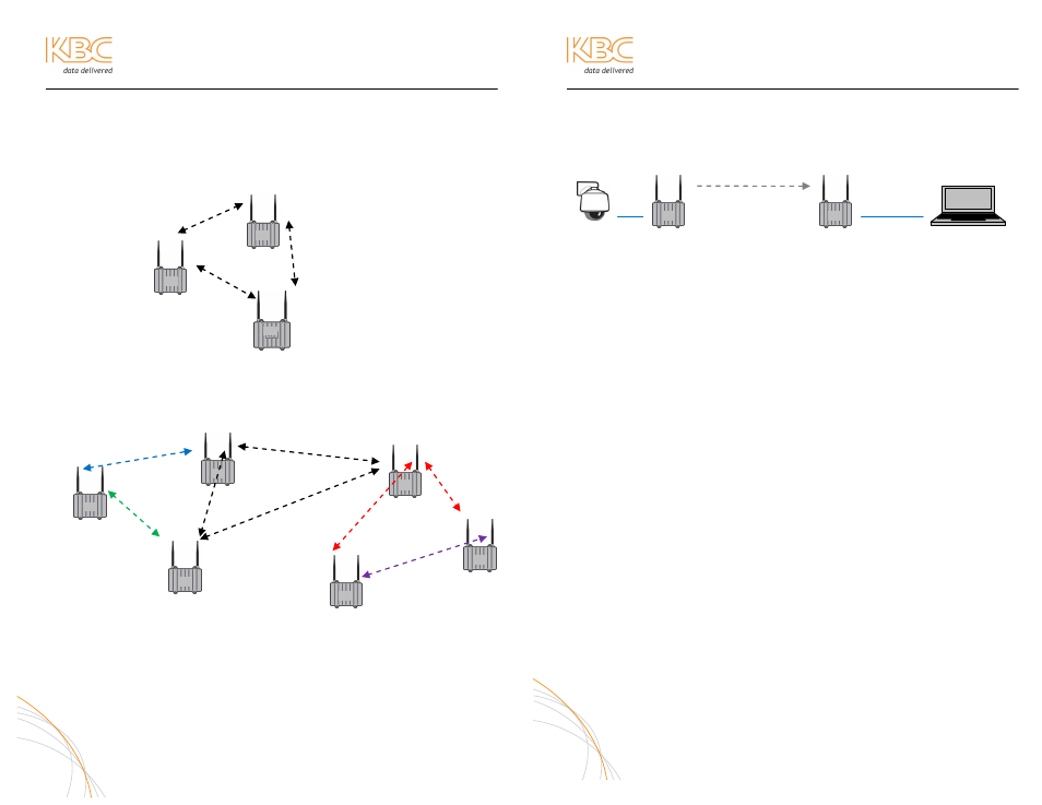
MESH TOPOLOGY DESIGN
A true mesh topology is set up when a node can associate and communicate with at
least two other mesh nodes. However, for ideal mesh operability, keep design in the
topology to the extent that no more than two nodes come into any one radio. In
essence, the mesh topology would appear in triangles of communication so that
redundant paths are still established.
Example of triangle mesh
communication:
To add more nodes to the mesh network, the topology would be built as shown:
(For an understanding of WiFi-0, WiFi-1, mode and channel see page 18)
Remote Node 2
Remote Node 3
Remote Node 1
Remote Node 5
Head End Node
Remote Node 4
Frequencies and antenna gain options are shown for illustration purpose only. A site
survey is the optimal way to determine frequency selection in a given environment. A
frequency can be also be selected using the RSSI and rate figures as described on
page 12 of this manual. In some environments additional nodes may be necessary to
reduce the number of hops while enabling redundant paths.
7
WES Mesh Wireless System Operations Manual
NODE INSTALLATION & OPERATION
A. PERFORM COMMAND PROMPT TEST
1. Connect the Mesh nodes to a laptop as shown in the following
diagram (default settings for node 1 & 2 shown):
IP: 192.168.1.21 IP: 192.168.1.20
IP: 192.168.1.10
IP: 192.168.1.x
ID: 02
ID: 01
WiFi-0: 11a, 165
WiFi-0: 11a, 165
WiFi-1: Disabled
WiFi-1: Disabled
2. Open Command Prompt from the Start Menu/Programs/Accessories
3. Allow approximately 45 seconds, then ping the IP addresses shown on
the configuration table included in the shipment.
a. Ping the connected node (ping 192.168.1.10)
b. Ping the wireless node (ping 192.168.1.20)
c. Ping the camera/encoder (ping 192.168.1.xxx)
d. Open a web browser and access the camera interface
8
WiFi-0:
11a 149
WiFi-1: 11a 165
WiFi-0:
11a 165
WiFi-1:
11g 6
WiFi-0:
11g 6
WiFi-0:
11a 149
WiFi-1:
11a 157
WiFi-0:
11a 157
WiFi-1:
11a 165
WiFi-0:
11g 6
WiFi-1:
11a 153
WiFi-1:
11a 153
Note:
Note:
Managed Switch using Spanning
Tree Protocol connected to one of
the mesh nodes is required for
ring/redundant configurations.
Note:
Managed Switch using Spanning Tree Protocol connected to one of
the mesh nodes is required for ring/redundant configurations.
If all three radios are active and
communicating in the format
pictured
at
left,
different
frequencies would be used. All
WiFi-0 primary radios can be
configured to one particular
frequency while all WiFi-1 radios
are set to a separate common
frequency
in
order
to
communicate in a mesh format.
To enable in this topology, MAC
filtering must be enabled on each
radio. For help with MAC filtering,
see appendix A-2.