Junger Audio d06 - Digital Audio Leveler User Manual
Page 18
3. INSTALLATION
operation manual d06, chapter 3 - Installation - page 4 of 10
The digital audio level processor d06 can be remote-controlled by means of
parallel GPI inputs.
Use to :
* recall of PRESETs 1-4
* switch between STEREO / 2CH link mode
* selection of INPUT 2 / 1
* switching the device to BYPASS
Connector :
D-SUB 15pin, female
Pin assignment of the connector :
Pin
Signal name
Functions
1
GPI1 in
Defined by d06 config
2
GPI2 in
Defined by d06 config
3
GPI3 in
Defined by d06 config
4
GPI4 in
Defined by d06 config
5
GPI5 in
Defined by d06 config
6
GPI6 in
Defined by d06 config
7
GPI7 in
Defined by d06 config
8
GPI8 in
Defined by d06 config
9 +
5V
110
Ω
10 GPI1/GPI2
common
11 GPI3
common
12 GPI4
common
13 GPI5
common
14 GPI6
common
15 GPI7/GPI8
common
Shield
-5V
GND of d06 Chassis
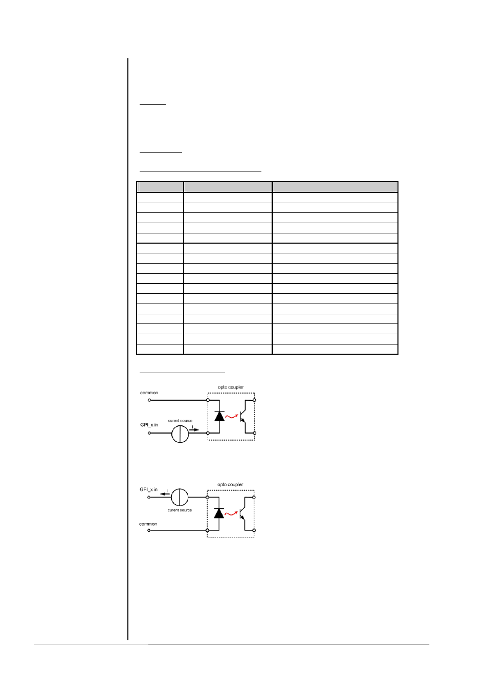
Electrical specification :
GPI input
potential free by opto-coupler in line with
a current source
ON:
+3.5…+30V
between
GPIx
input
and GPx common
OFF:
less then 1.5V between GPIx input
and GPIx common
For serial numbers S/N 59 and higher (HW Revision 2a and higher) the
polarity of the GPI inputs has been changed. to make use of the internal
ground based
auxiliary 5 V for "low active" switching.
ON:
-3.5…-30V
between
GPIx
input
and GPx common
OFF :
less then 1.5V betwee GPIx input
and GPIx common
Signal duration must be at least 50msec.
Note :
An internal auxiliary voltage feed of +5V is available on pin 9
via a 110 Ω resistor. Ground is available from the shield of the connector
only! When using the auxiliary voltage feed, there is no electrical isolation
given anymore and the risk to inject unwanted noise is high!
Important Note :
You must take care about the polarity of the external voltage
applied to the GPIs.
Wrong polarity
may
destroy electronic components
and may
cause fire
inside the d06!
3.7.2
GPI