Junger Audio b45 - Digital Audio Delay User Manual
Page 12
2. FUNCTION DESCRIPTION
2.7.2
AUTO TRACKING
BY TTL CONTROL
SIGNAL
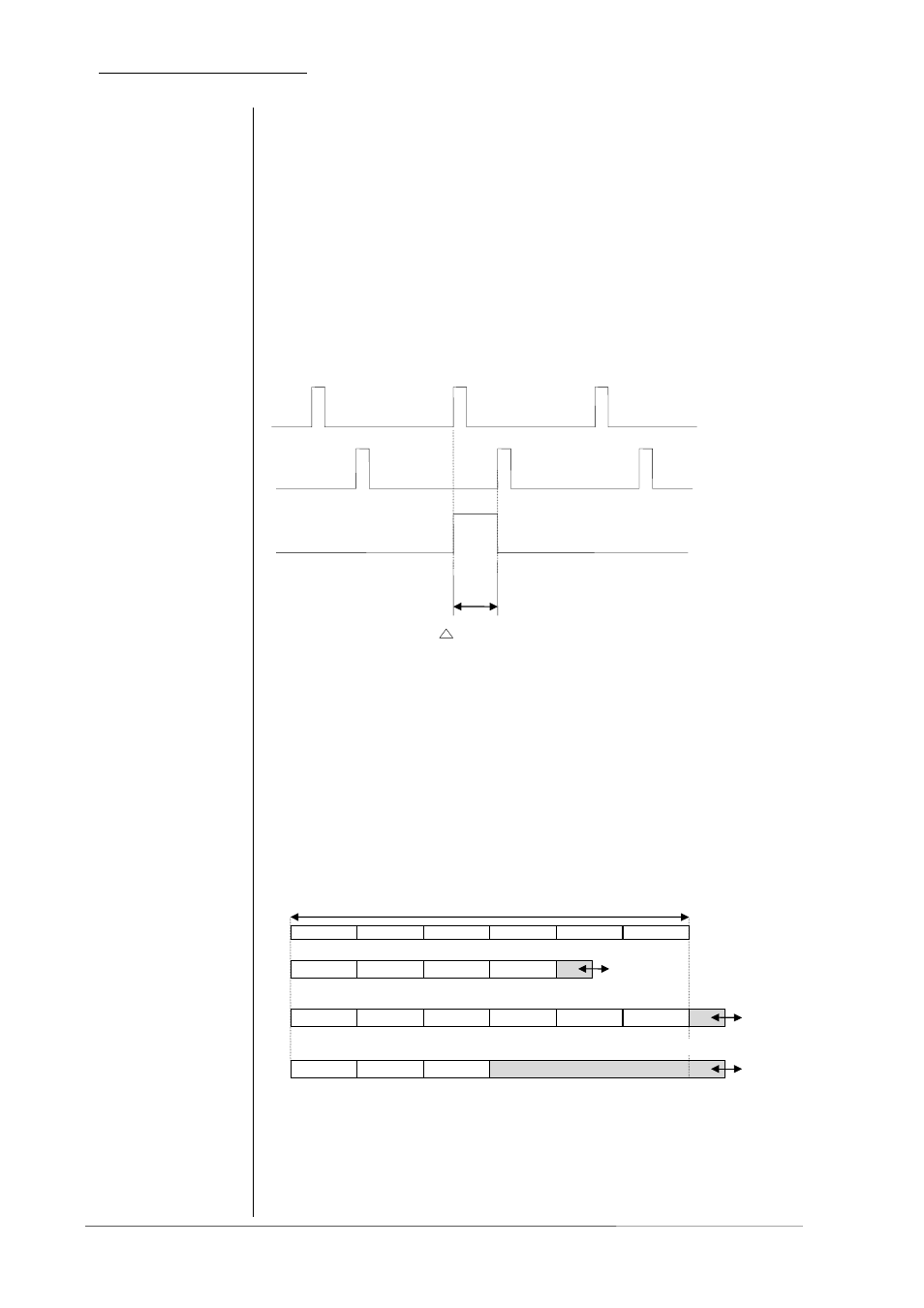
The digital audio delay b45 can generate the auto tracking
control signal by using a TTL control signal. To calculate the auto
tracking delay time the detection circuit is measuring the HIGH
period of the TTL input signal. The length in time of the HIGH
period is used as delay time for auto tracking. The maximum
delay time shouldn’t be more as the maximum memory capacity
of the delay (see technical specifications). Otherwise it produces
a memory overflow and an error message will be displayed.
Every new positive pulse at TTL input is measured and is
overwriting the last calculated value.
page 2-6 operation manual b45, chapter 2 -Function description-
VIDEO
SYNC
VIDEO
TRACKING
TTL PULSE
t
vt
- tracking delay time
t = t
vt
2.7.3
AUTO TRACKING
WITH OFFSET
There is the possibility to activate auto tracking even if a fixed
delay time is preadjusted. The already adjusted delay time is an
offset to the auto tracking delay time. Please note that the overall
delay time consisting of delay offset and auto tracking delay time
shouldn’t be more as the maximum memory capacity of the
delay (see technical specifications). Otherwise it produces a
memory overflow and an error message will be displayed. The
use of the unit is blocked to prevent deteriorated audio signals at
digital output.
t
vmax
= maximum memory capacity per channel
auto tracking video with offset, error message overflow
auto tracking video with offset
auto tracking TTL with offset, error message overflow
Note! In auto tracking TTL auto tracking delay time can be
longer as one videoframe!