Ivie iFlex 2400 Series User Manual
Page 6
4
to 0.
13. Show Text Output - Allows the user to place
text on the layout area that is associated
with a control.
14. Font - Sets the font of the text to be placed.
15. Color - Sets the color of the text to be
placed.
Doors
The display method for doors is different than other placement
elements. The door icon is a smart icon that orients the door vertically or
horizontally depending on how the user sizes the icon. If the horizontal
length is greater than the vertical length, the door orientation will be
horizontal. The best method for learning how to orient doors is to practice
resizing the icon, and view how the door orientation responds.
A note on iFlex
TM
/Sonata
TM
controls
The iFlex hardware and firmware treat each control as having three
elements - a level, a switch, and an output or LED. If controls are hard-
wired to the 12 ports on the rear panel of an iFlex mixer, then a total of 12
pots, 12 switches, and 12 LEDs are possible.
To accomodate a larger number of controls, iFlex uses the RS485 protocol
and smart controls to multiply the number of controls allowed in a
system. Communicating digitally, each iFlex mixer allows up to 128 sets
of 3 controls ( 1 switch, 1 level, and one output/led). The RMPC line of
control boards also allow any custom control or set of controls to act as
a smart control, effectively providing a large number of controls for any
system requirement.
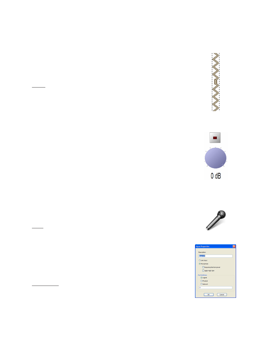
Input
To place an input (line or microphont), right-click in the layout area, and
select ‘Create Input’. An icon of a microphone will be placed at the
current mouse location. To change the properties of the input, right-
click on the icon, and select ‘Properties’. A properties dialog box will
allow the user to select between a microphone or line input, as well
as phantom power and high gain. There are also options for the port
definition (logical, and physical).
Output Zone
Output zones are created in Sonata
TM
as colored polygonal regions. To
create an output zone, right-click anywhere on the layout area and select
‘Create Output Zone’. The mouse cursor will change to a crosshair,
ready to place the first polygon point. As points are placed the shaded
region will begin to take shape. When the desired region is complete, a