Wiring diagrams, 1 single channel dimming, Page 8 – CP Electronics MWS3A-DD User Manual
Page 8
page 8
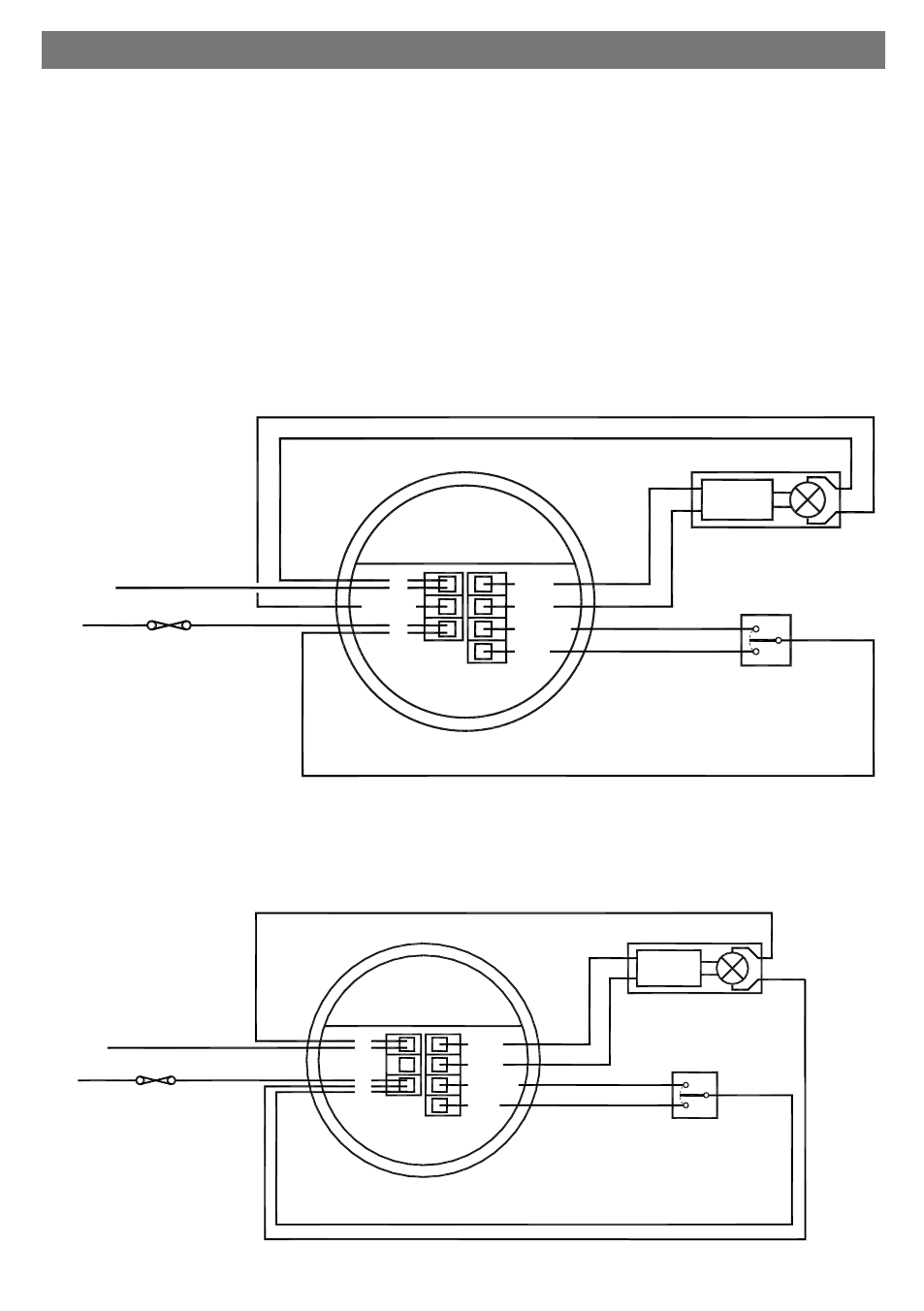
10. Wiring Diagrams
6.1 Single channel dimming
Functions: Switches the luminaire with occupancy and maintains illuminance. Dims and switches using
optional centre biased retractive switch (MK K4900 or similar).
Configured to presence detection: Turns on automatically with occupancy. Maintains illuminance.
Press and release down switch to turn off. Press and release up switch to turn back on. Press and hold up
switch to dim up, press and hold down switch to dim down. Turns off after occupancy.
Configured to absence detection: Press and release up switch to turn on. Maintains illuminance. Press
and release down switch to turn off. Press and hold up switch to dim up, press and hold down switch to
dim down. Turns off after occupancy.
Channel mode: Set to ―Switch and dim together‖.
Switch mode: Set to ―2 position switch together‖.
-
+
L/OUT
L
N
EBDSPIR-DD SENSOR
SW1/UP
DIM+
DIM-
SW2
DOWN
DIMMING
BALLAST
DIMMING LUMINAIRE
(DSI or DALI)
CIRCUIT PROTECTION
(IF REQUIRED)
LIVE
NEUTRAL
CENTRE BIASED
RETRACTIVE SWITCH
(240V SWITCHING)
Optional for presence,
mandatory for absence detection
L/OUT
L
N
EBDSPIR-DD SENSOR
SW1/UP
DIM+
DIM-
SW2
DOWN
DIMMING
BALLAST
DIMMING LUMINAIRE
(DSI or DALI)
CIRCUIT PROTECTION
(IF REQUIRED)
LIVE
NEUTRAL
CENTRE BIASED
RETRACTIVE SWITCH
(240V SWITCHING)
Optional for presence,
mandatory for absence detection
MWS3A-DD SENSOR
MWS3A-DD SENSOR
When there is a requirement to have an ‗Off‘ state that requires a permanent dimmed level. Then use the
DSI / DALI ―pair‖ to both switch and dim, and a live feed direct to the ballast. Set the ‗Off value‘ (section
4.10 in the Programming section) to a value greater than zero to achieve a permanent dimmed level for
the ‗Off‘ state. See the diagram below for wiring details.