Hybrid regulator, Product description, Capacitor bank components – CIRCUTOR OPTIM HYB Series User Manual
Page 8
2.- PRODUCT DESCRIPTION
The purpose of this manual is to assist during the installation, start-up and maintenance of
OPTIM HYB series low voltage (LV) capacitor banks with static operation. Carefully read the
manual to achieve the best performance from those units.
2.1.- CAPACITOR BANK COMPONENTS
From the electrical standpoint, the unit is made up of the following blocks:
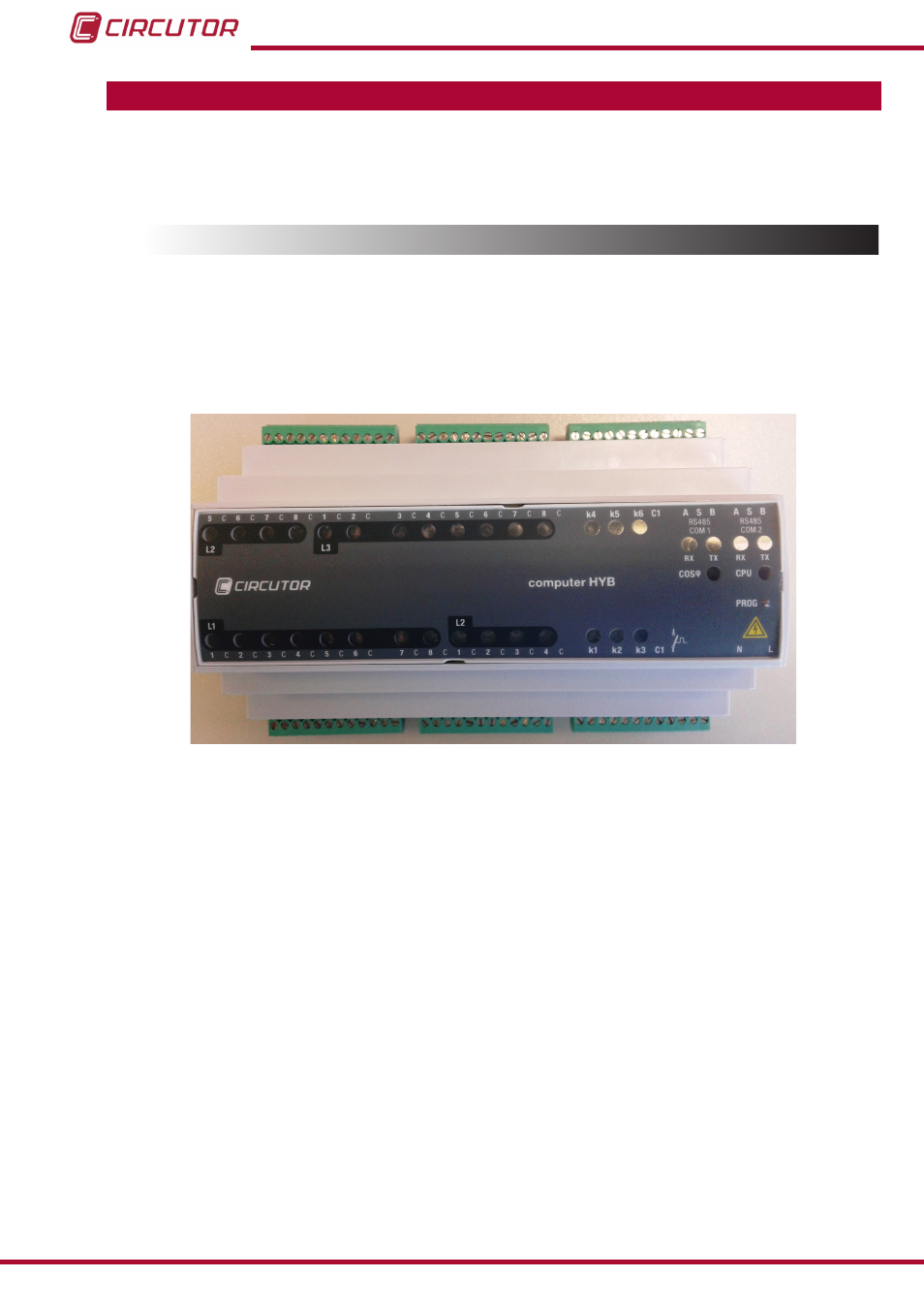
2.1.1. HYBRID REGULATOR
The hybrid capacitor banks are equipped with
Computer HYB hybrid regulators (
).
Figure 3:
Computer HYB Hybrid Regulator.
This regulator has two types of outputs (see the inputs and outputs identified in
.
:
6 relay outputs with operating voltage of 250 V ~. and operating current of 4 A (AC1) for
the auxiliary control voltage of the electromechanical contactors that operate the three-phase
capacitors (three-phase steps of the
OPTIM HYB capacitor bank).
24 static outputs to provide a 12 Vdc activation signal to the + and - inputs of the CPC2
connection controller boards at zero voltage difference. These boards control the semiconduc-
tor modules (thyristor-diode) and operate the single-phase capacitors (single-phase steps of
the
OPTIM HYB capacitor bank).
The
Computer HYB also has the following notable features:
The necessary information to calculate compensation demand by phase is provided by a
CVM-MINI-RS485-model power analyzer via RS-485 communications with the Modbus/RTU
protocol.
8
OPTIM HYB Series
Instruction Manual