External isolation and protection elements, Auxiliary control voltage, Earth cable connection – CIRCUTOR OPTIM HYB Series User Manual
Page 19
3.6.- EXTERNAL ISOLATION AND PROTECTION ELEMENTS
The capacitor bank has a manual internal quadrupole isolator, but it must be connected to a
line that is protected by a circuit breaker as well as earth leakage protection at the header, in
accordance with Spanish Low-Voltage Electrotechnical Regulations (LVR) and depending on
the earthing system of the installation.
The protection elements, isolation switches and/or switches that are added exter-
nally to the capacitor bank must be of a minimum size to withstand a current 1.5
times greater than what is indicated on the label (LVR, ICT-BT-48)
If an earth leakage protection for the capacitor bank is installed, its sensitivity and
trip delay must be adjustable.
3.7.- AUXILIARY CONTROL VOLTAGE
Standard
OPTIM HYB capacitor banks for 3 x 400 V / 1 x 230 V networks do not require an
auxiliary power supply.
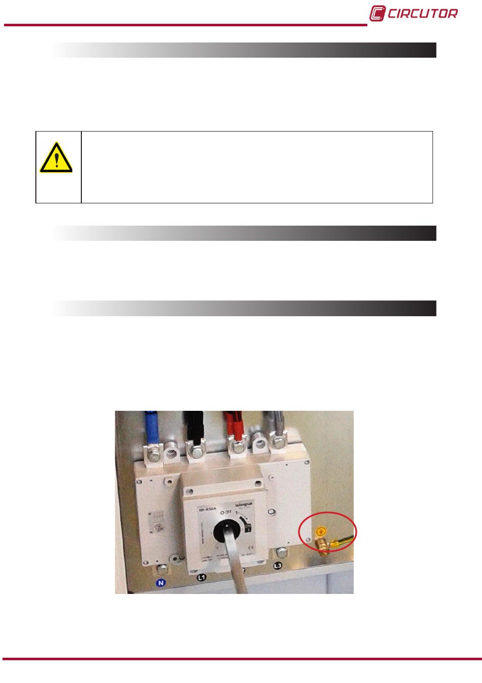
3.8.- EARTH CABLE CONNECTION
Connect the earth terminal of the capacitor bank housed inside the operations panel of the unit
(see
to the exterior earth connection.
The earth cable section must be selected in accordance with the admissible current limits es-
tablished in the LVR (ITC-BT-19 – Indoor or receiver installations).
Figure 10: Earthing terminal for external earthing connection of the OPTIM HYB capacitor banks
19
Instruction Manual
OPTIM HYB Series