Current transformer (ct) connection – CIRCUTOR OPTIM HYB Series User Manual
Page 20
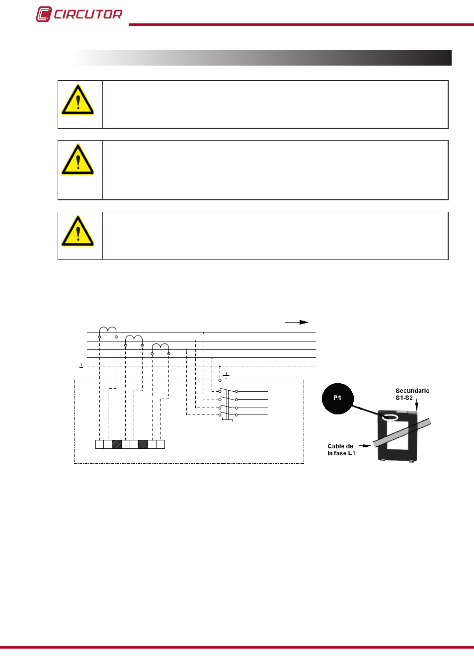
3.9.- CURRENT TRANSFORMER (CT) CONNECTION
For standard units that come with a CVM-MINI-RS485 power analyzer: You
must place 3 current transformers (CT) outside the capacitor bank, one at
each phase, measuring the total current of the load plus the capacitor bank
itself (
The standard transformer must have a nominal output of 5 A at the secondary.
For correct measurement of powers and angles, you must connect the CT to
each phase with the direction of the current from P1 to P2 (
) and connect
the secondary (terminals S1, S2) to the terminals with the same name on the ca-
pacitor bank (see
).
Avoid the flow of current through the CT's primary before connecting the second-
ary to the S1 and S2 terminals of the capacitor bank.
If the CT must be installed while the installation is under load, short-circuit S1 and
S2 while they are not connected to the capacitor bank.
The current value of the CT primary winding must be equal to or slightly greater than the size of
the mains switch of the installation. Therefore, the CT must be able to measure the maximum
current expected to be consumed by all the loads being compensated.
L1
L2
L3
N
RED
CARGA
3x400 V / 1x230 V - 50 Hz
L1
L2
L3
S1
N
TB1
BATERÍA DE
CONDENSADORES
1S1 1S2
S1
S2
S1
S2
S1
S2
T.I.1
T.I.2
T.I.3
2S1 2S2
3S1 3S2
Figure 11: Installation of external current transformers (CT).
The connection point of the CT for a capacitor bank that compensates an entire installation is
after the mains switch of the installation.
To prevent excessive attenuation of the signal, it is recommended that the minimum secondary
section winding cable size (terminals S1, S2) is at least
2.5 mm
2
.
20
OPTIM HYB Series
Instruction Manual