Installation, Unit terminals – CIRCUTOR CEM-C30 series User Manual
Page 9
3.2.- INSTALLATION
On the side of the unit are all of the indications adjusted to the CEI 62052-11 standard.
The unit is installed on a DIN rail. All connections are located inside the electric panel.
Terminals, opening covers or removing elements can expose parts that are haz-
ardous to the touch while the unit is powered. Do not use the unit until it is fully
installed.
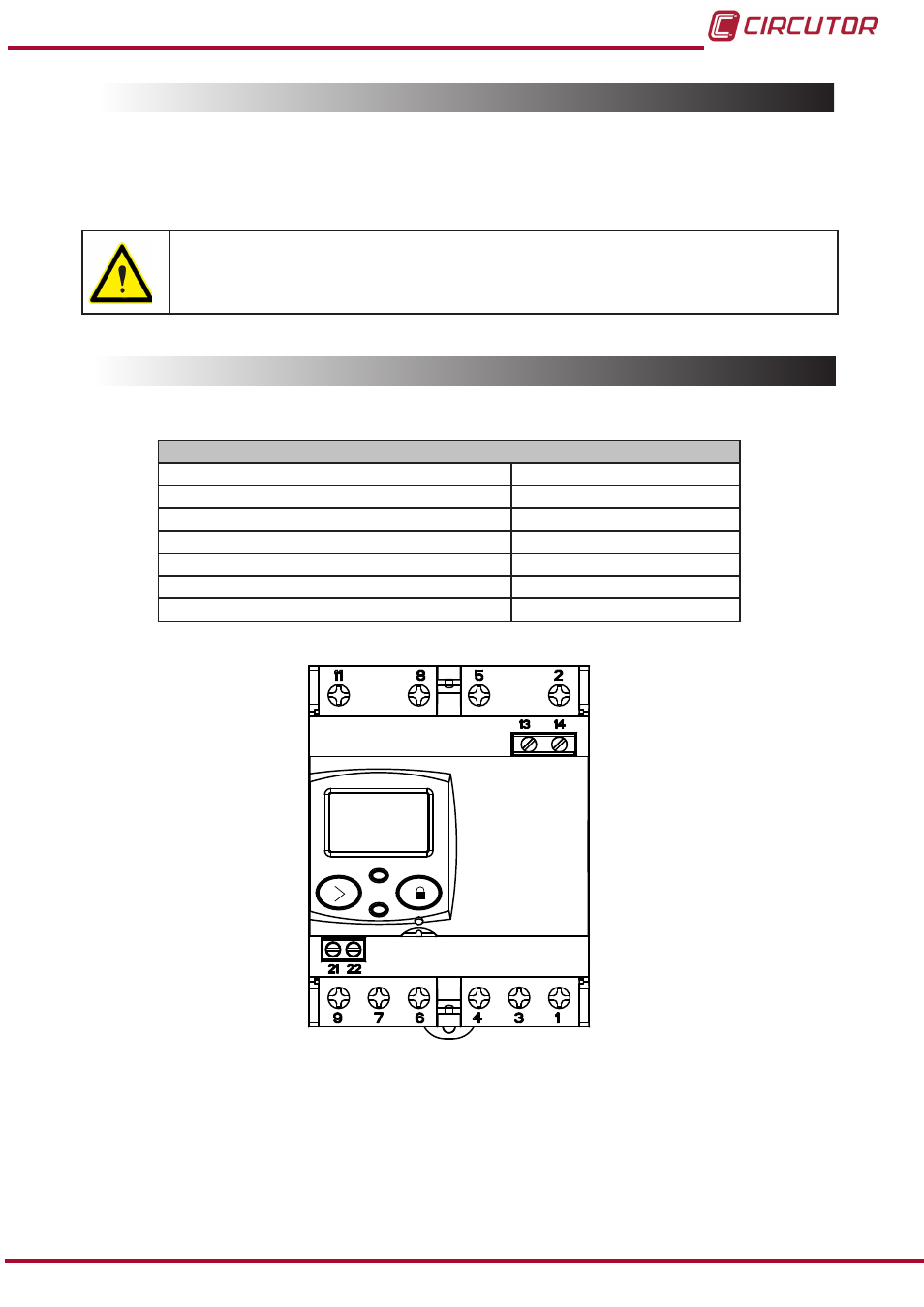
3.3.- UNIT TERMINALS
Table 3:List of CEM-C30 terminals�
Unit terminals
1 : S1, Current input L1
8 : L3, Voltage input L3
2 : L1, Voltage input L1
9 : S2, Current output L3
3 : S2, Current output L1
11 : N, Neutral connection
4 : S1, Current input L2
13 : Auxiliary Power Supply
5 : L2, Voltage input L2
14 : Auxiliary Power Supply
6 : S2, Current output L2
21 : Impulse output (Collector)
7 : S1, Current input L3
22 : Impulse output (Emitter)
Figure 1:Terminals of the CEM-C30�
9
Instruction Manual
CEM-C30