Lead-out of signals – CIRCUTOR DHB Series User Manual
Page 9
9
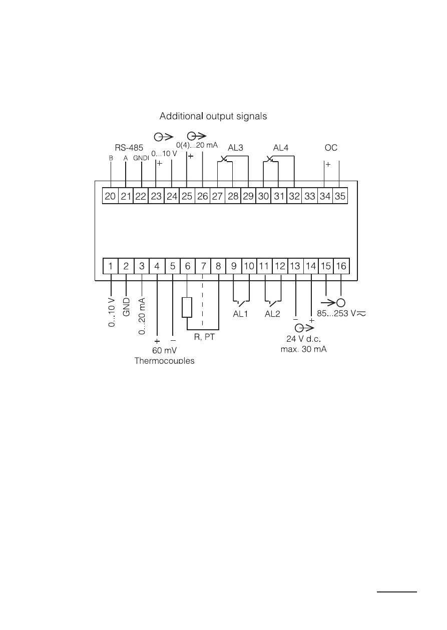
4.1. Lead-out of Signals
Signals led out on the meter connectors are presented on the fig. 4.
Circuits of successive groups of signals are separated between them.
Fig. 4. Description of Signals on Connection Strips
(Model DHB-424)
DHB-402 / DHB-424
· 0...10 V – input for the measurement ±10 V voltage,
· GND – mass for the 0...10 V input and 0...20 mA input,
· 0...20 mA – input for the measurement of ±20 mA current,
· 60 mV TC – input for the measurement of 60 mV voltage, or for the
connection of RTD sensors,
· R, PT – input for the resistance measurement or for the connection
of RTD sensors. The compensation wire has been marked by
a broken line,
· OC – open collector output of npn type– signaling of the measuring
range overflow.
See also other documents in the category CIRCUTOR Measuring instruments:
- CVMk2 Series (152 pages)
- QNA500 series (111 pages)
- Wi-beee Series (32 pages)
- CVM-C5 Series (40 pages)
- CVM-C10 Series (82 pages)
- CVM-MINI Series (26 pages)
- CVM-NET Series (2 pages)
- CVM-NET4 (7 pages)
- CVM-1D Series (2 pages)
- CVM-BDM Series (32 pages)
- PowerNet Series (2 pages)
- CVM-NRG96 Series (Available until stocks) (38 pages)
- CVM-B Series (320 pages)
- CVM96 Series (44 pages)
- CVM144 Series (58 pages)
- RS2RS (2 pages)
- TCP1RS+ (2 pages)
- EDS Series (5 pages)
- CMBUS series (24 pages)
- EDS-3G Series (6 pages)
- MDC-4 (30 pages)
- LM50-TCP+ (2 pages)
- MDC-20 (58 pages)
- ReadWatt Series (22 pages)
- CIRLAMP Series (102 pages)
- PowerStudio Series (42 pages)
- PowerStudio Series (110 pages)
- PowerStudio Series (110 pages)
- PowerStudio Series (292 pages)
- OPC Server PS/PSS (22 pages)
- SQL Data Export (28 pages)
- AR6 Series (69 pages)
- AR5L Series (52 pages)
- CIRe3 Series (50 pages)
- CIReQ (36 pages)
- QNA-P Series (36 pages)
- T3V Series (8 pages)
- CPM (Available until stocks) (20 pages)
- DHB Series (58 pages)
- DHB Series (46 pages)
- DHB Series (54 pages)
- EMF-EMB Series (11 pages)
- SYNCHROMAX Series (2 pages)
- SYNCHROMAX Series (2 pages)