Analog input, 25 swm24 hardware manual – Applied Motion SWM24IP-3EE User Manual
Page 25
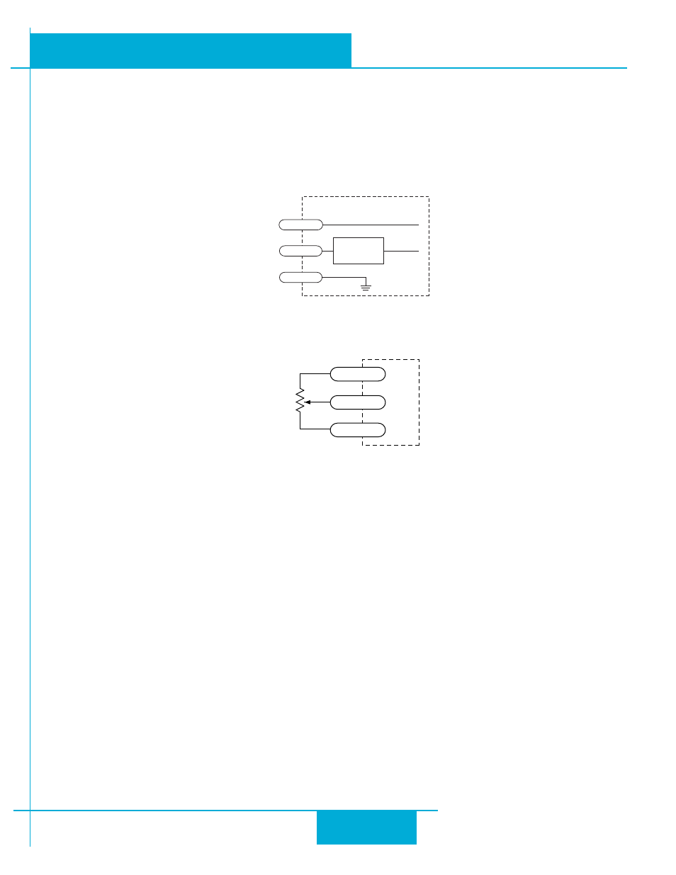
Analog Input
All SWM24 drives feature an analog input. The input can accept a signal range of 0 to 5 VDC. The drive can be con-
figured to operate at a speed or position that is proportional to the incoming analog signal. Use the
ST Configurator™
software to set the signal range, offset, dead-band and filter frequency. The SWM24 provides a +5VDC 50ma output
that can be used to power external devices such as potentiometers. It is not the most accurate supply for reference; for
more precise readings use an external supply that can provide the desired accuracy.
Analog Input Circuit
Connecting a Potentiometer to the Analog Input
inside drive
AIN
GND
Signal
Conditioning
+5V
50 mA max
I/O
Conne
ct
or
1-10k
pot
cw
ccw
GND
AIN
+5V OUT
25
SWM24 Hardware Manual
920-0068B
10/31/2013