Inputs and outputs (-sf and -qf), 21 swm24 hardware manual – Applied Motion SWM24IP-3EE User Manual
Page 21
Inputs and Outputs (-SF and -QF)
The SWM24SF and SWM24QF have four “flex I/O” points. Each can be configured as a digital input or a digital out-
put. In addition, pre-defined functions such as motor enable or fault output can be assigned, providing the flexibility to
handle a diverse range of applications.
ST Configurator™
is used to set each flex I/O point as an input or output.
ST Configurator™
can also be used to assign
functions to each I/O point, or functions can be assigned “on the fly” from SCL streaming commands or stored Q pro-
grams. Example connection diagrams can be found on the following pages.
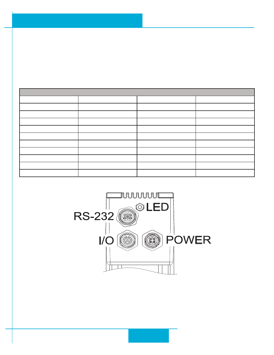
SWM24 Connectors
Refer to connection charts at the end of this manual for wire colors on mating cables.
I/O Functions (configure in software)
I/O 1
I/O 2
I/O 3
I/O 4
Step Input
Direction Input
Jog CW Input
Jog CCW Input
Limit CW Input
Limit CCW Input
Enable Input
Alarm Reset Input
Enable Input
Alarm Reset Input
Start/Stop Input
Change Speed Input
General Purpose Input
General Purpose Input
General Purpose Input
General Purpose Input
Brake Output
Brake Output
Brake Output
Brake Output
Fault Output
Fault Output
Fault Output
Fault Output
Motion Output
Motion Output
Motion Output
Motion Output
Tach Output
Tach Output
Tach Output
Tach Output
General Purpose Output General Purpose Output General Purpose Output General Purpose Output
21
SWM24 Hardware Manual
920-0068B
10/31/2013