Cpld configuration using external usb-blaster, Status elements, Cpld configuration using external usb-blaster –6 – Altera MAX V CPLD Development Board User Manual
Page 12: Status elements –6
2–6
Chapter 2: Board Components
Configuration, Status, and Setup Elements
MAX V CPLD Development Board Reference Manual
January 2011
Altera Corporation
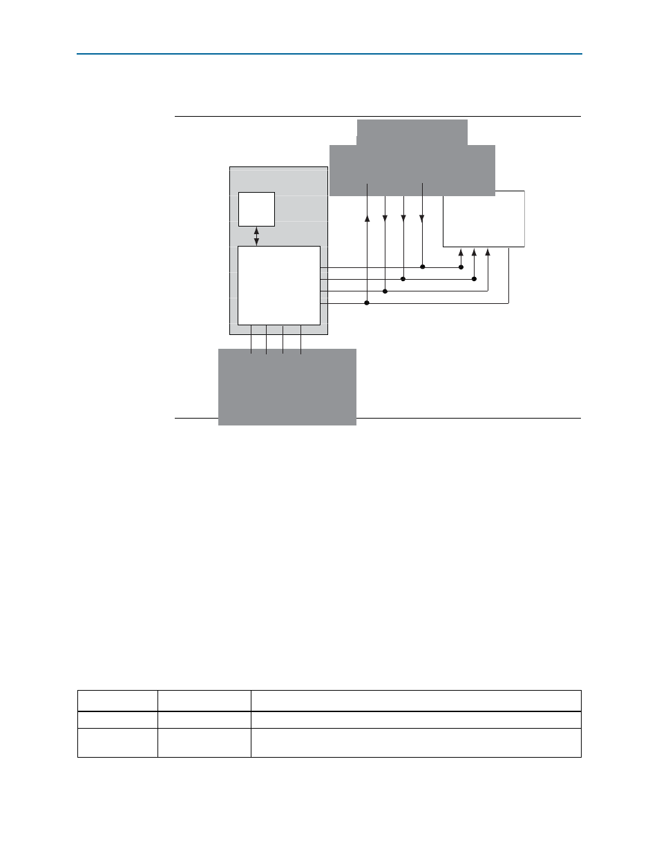
illustrates an exmaple of the JTAG chain connection.
The primary configuration mode for the MAX V CPLD is via JTAG using the MAX II
configuration controller design (embedded USB-Blaster). The board also includes a
JTAG connector which interfaces directly to the MAX V CPLD as the alternate source
for configuration.
CPLD Configuration using External USB-Blaster
The JTAG programming header (J13) provides another method for configuring the
CPLD using an external USB-Blaster device with the Quartus II Programmer running
on a PC. The external USB-Blaster connects to the board through the JTAG connector.
illustrates the JTAG chain.
Status Elements
This section describes the status elements. The development board includes two
status LEDs which connects to the MAX V CPLD.
lists the LED board references, names, and functional descriptions.
Figure 2–3. JTAG Chain
MAX V CPLD
5M570ZF256C5N
TCK TMS TDI TDO
MAX II
EPM240M100
Embedded USB-Blaster
GPIO (TCK)
GPIO (TMS)
GPIO (TDO)
GPIO (TDI)
TCK
TMS
TDI TDO
USB
PHY
(Connector not mounted)
(Connector not mounted)
Table 2–5. Board-Specific LEDs
Board Reference
LED Name
Description
D1
Power
Blue LED. Illuminates when power is active.
D3
USB
Green LED. Illuminates when the embedded USB-Blaster is in use. Driven by the
MAX II CPLD EPM240M100.