Nexen TL 10 - 15 801570 User Manual
Page 9
6
FORM NO. L-21185-B-1209
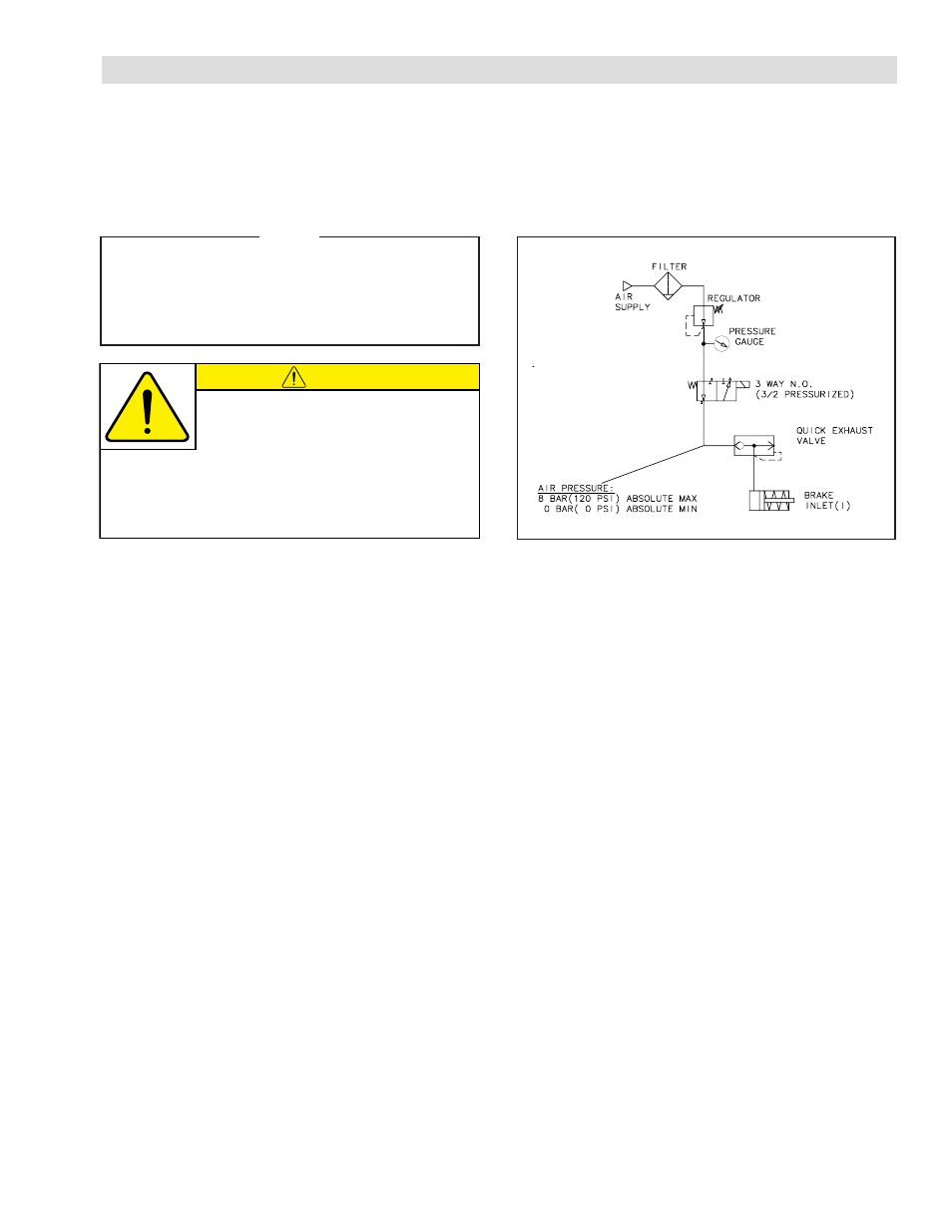
AIR CONNECTIONS
The following are common air supply schemes used with
this product. These are examples and not an all-inclusive
list. All air circuits to be used with this product must be
designed following EN983 guidelines.
All Nexen pneumatically actuated devices require clean,
lubricated air for maximum performance and long life. This
air must meet or exceed ISO 8573.1:2001 Class 4.4.3
quality. Your Nexen Distributor carries filters and lubrica-
tors specifically designed to operate with Nexen products.
NOTE
Nexen recommends the Air Regulator used
with Torque Limiters is a Constant Bleed Type
used together with a 3-Way Solenoid Valve to
ensure a total “crisp” release upon an overload
condition.
CAUTION
Do not use rigid pipe or tubing when making
air line connections. Torque on the air line
caused by bearing drag may be relieved
by resting the air line on a support parallel to the Torque
Limiter centerline. Align air inlet port to the six o’clock
down position to allow condensation in the air chamber
to drain out of the exhaust port.
SINGLE AIR PRESSURE CONTROL SYSTEM
Nexen’s Single Air Pressure Control System consists of: Constant Bleed Type Regulator, Gauge, Quick Exhaust Shuttle
Valve, Tee Fitting, 3-Way N.C. (Normally Closed) Solenoid Valve, and Air Line.
DUAL AIR PRESSURE CONTROL SYSTEM
Nexen’s Dual Air Pressure Control System consists of: Air Filter, Air Regulator, Constant Bleed Type Regulator, two Tee
Fittings, two 3-Way N.C. (Normally Closed) Solenoid Valves, Timer Delay Control, two Quick Exhaust Shuttle Valves, Gauge,
and Air Line.