Nexen TL 10 - 15 801570 User Manual
Page 14
11
FORM NO. L-21185-B-1209
TORQUE LIMITER REMOVAL & DISASSEMBLY
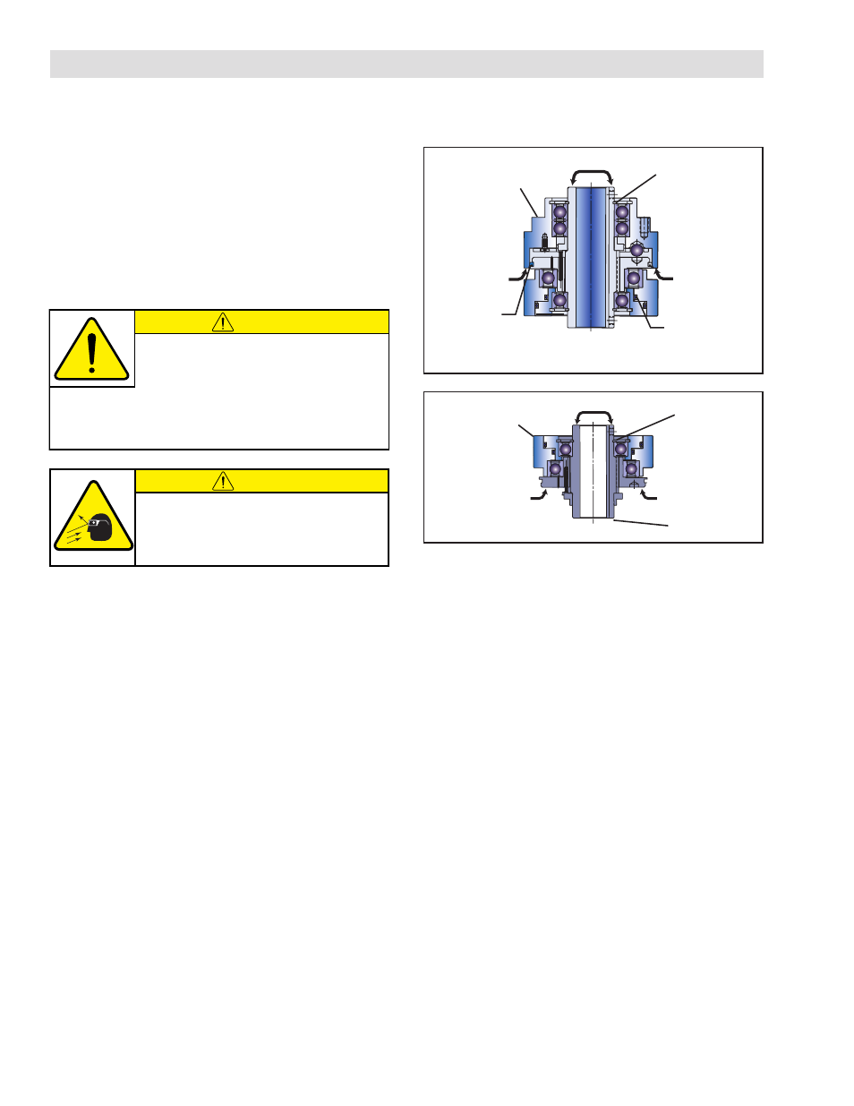
REFER TO FIGURES 13 & 14.
1. Shut off machine and air supply to the Torque
Limiter.
2. Disconnect the Torque Limiter from the air supply by
removing the Quick Exhaust Shuttle Valve and the
3-Way N.C. Solenoid Valve.
3. Remove the Torque Limiter from the machine.
Drive Flange
Assembly
(Item 19)
Cylinder/Piston
Assembly
(Items 8 and 9)
FIGURE 13
FIGURE 14
Rotary Seal
(Item 15)
Retaining Ring
(Item 6)
Press
Support
Support
PARTS REPLACEMENT
CAUTION
Correct alignment of Torque Limiter internal
components is critical for proper operation
of the Torque Limiter. Before disassembly,
mark Hub, Cylinder, and Drive Flange with chalk alignment
marks to ensure correct alignment of internal components
when reassembling Torque Limiter.
4. Remove the Retaining Ring (Item 6) from the Hub
(Item 7) on the Drive Flange Assembly (Item 19) end
of the Torque Limiter.
5. Supporting Drive Flange Assembly (Item 19), press
Hub (Item 7) and Cylinder/Piston Assembly out of
Drive Flange.
6. Remove the Rotary Seal (Item 15) from the Cylinder/
Piston Assembly (Items 8 and 9).
7. Remove Retaining Ring (Item 6) from Hub (Item 7)
on Cylinder/Piston end of Torque Limiter.
8. Supporting Cylinder/Piston Assembly, press Hub
(Item 7) out of Cylinder/Piston Assembly.
Cylinder/Piston
Assembly
(Items 8 and 9)
Hub (Item 7)
Retaining Ring
(Item 6)
Support
Press
Support
CAUTION
Working with spring loaded or tension
loaded fasteners and devices can cause
injury. Wear safety glasses and take the
appropriate safety precautions.