Introduction hub preparation – Nexen TL 10 - 15 801570 User Manual
Page 5
2
FORM NO. L-21185-B-1209
INTRODUCTION
HUB PREPARATION
Nexen's air-engaged, single-position Torque Limiters provide overload protection for power transmission equipment, thus
protecting machinery or product from jam-ups and resultant down time expense.
The totally enclosed construction of Nexen's Enclosed Torque Limiter allows for usage in wet or humid conditions and is
acceptable for use in federally inspected meat and poultry plants.
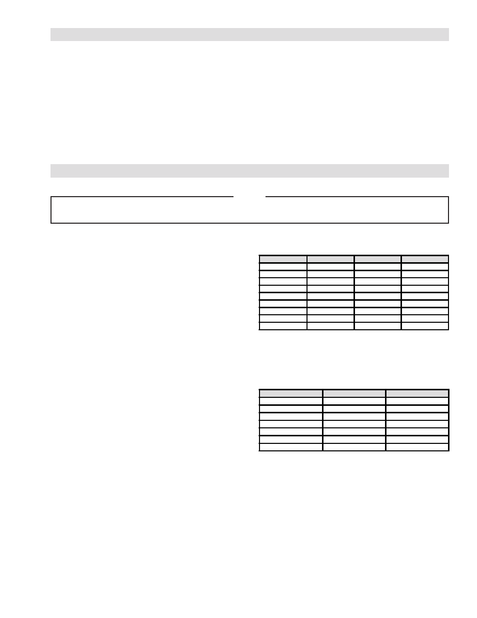
TABLE 1
TABLE 2
NOTE
This section pertains only to Torque Limiters finished bored by the customer. If your Torque Limiter has
been bored at the factory, proceed with INSTALLATION.
TL-A
After the Hub has been finished bored, drill and tap the Hub
for Set Screws. Set Screw locations are over the keyway,
and at 90º of the keyway. Models TL10-A and TL15-A
require two Set Screws located on the Drive Flange end
of the Hub. Models TL20-A and higher require two Set
Screws located on both ends of the Hub (Refer to Table 1
for Set Screw sizes).
TL-AC
After the Hub has been finished bored, make four saw cuts
in the Drive Flange end of the Hub. Locate the first saw
cut 45º from the keyway and the other three saw cuts at
90º increments from the first saw cut (Refer to Table 2 for
saw cut dimensions).
MODEL
US
METRIC
QTY
TL10-A
10-24
M5-0.8
2
TL15-A
10-24
M5-0.8
2
TL20-A
1/4-20
M6-1.0
4
TL30-A
5/16-24
M6-1.0
4
TL40-A
3/8-24
M10-1.5
4
TL50-A
3/8-24
M10-1.5
4
TL60-A
1/2-13
M12-1.75
4
TL70-A
1/2-13
M12-1.75
4
TL80-A
1/2-13
M12-1.75
4
MODEL
CUT WIDTH
CUT DEPTH
TL20-AC
0.06'' [1.52 mm]
0.96'' [25.4 mm]
TL30-AC
0.06'' [1.52 mm]
0.96'' [25.4 mm]
TL40-AC
0.06'' [1.52 mm]
0.96'' [25.4 mm]
TL50-AC
0.06'' [1.52 mm]
0.96'' [25.4 mm]
TL60-AC
0.06'' [1.52 mm]
0.96'' [25.4 mm]
TL70-AC
0.06'' [1.52 mm]
0.96'' [25.4 mm]
TL80-AC
0.06'' [1.52 mm]
0.96'' [25.4 mm]