Electrical connections, Caution – Nexen TL 10 - 15 801570 User Manual
Page 10
7
FORM NO. L-21185-B-1209
FIGURE 9
FIGURE 10
ELECTRICAL CONNECTIONS
LIMIT SWITCH
S
ingle
and
d
ual
a
ir
P
reSSure
S
yStemS
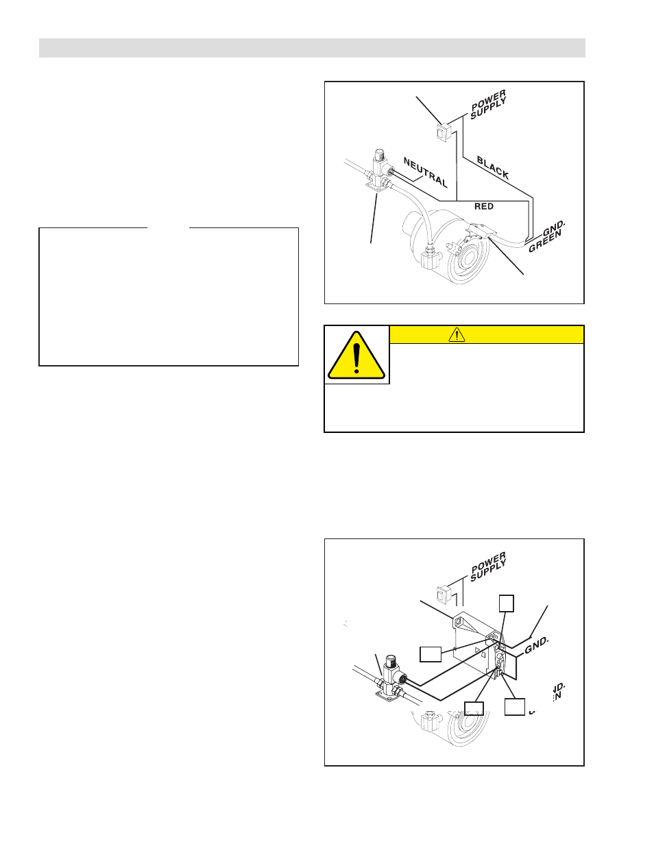
REFER TO FIGURE 9.
1. Connect the GREEN lead of the Limit Switch to
ground.
2. Connect the BLACK lead of the Limit Switch to a
110V power supply or customer supplied Reset
Switch.
NOTE
A customer supplied, manually operated, Reset
Switch may be installed between the Limit
Switch and 3-Way N.C. Solenoid Valve. This
allows the operator to apply running air pressure
to the Torque Limiter to aid in resetting the
Torque Limiter. Flexible electrical conduit must
be used when making electrical connections
between the Limit Switch, 3-Way Air Inlet N.C.
Solenoid Valve, and Power Supply. Do not use
rigid electrical conduit for these connections.
3. Connect one lead of the 3-Way N.C. Solenoid Valve
to the RED lead of the Limit Switch.
4. Connect the second wire of the 3-Way N.C.
Solenoid Valve to ground or neutral.
3-Way N.C.
Solenoid Valve
Reset
Switch
Limit
Switch
CAUTION
The WHITE wire on the Limit Switch is used
only when connected to a Normally Open
(N.O.) Solenoid Valve. Tape off the end
of the WHITE wire when using Normally Closed (N.C.)
Solenoid Valves. Voltage is present at the WHITE wire
when the Limit Switch is actuated to the open condition.
TIMER DELAY CONTROL
d
ual
a
ir
P
reSSure
C
ontrol
S
yStem
REFER TO FIGURE 10.
1. Connect Terminal A1 of the Timer Delay Control to a
power supply.
2. Connect one lead wire of the 3-Way N.C. Solenoid
Valve to Terminal A1 of the Timer Delay Control.
3. Connect the other lead wire of the 3-Way N.C.
Solenoid Valve to Terminal 16 of the Timer Delay
Control.
4. Connect the Jumper wire between Terminals 15 and
A2 of the Timer Delay Control to ground.
A1
16
15
A2
3-Way N.C.
Solenoid Valve
To Power
Supply
Timer Delay
Control