Hot water generator connections, Water tank preparation, Plumbing installation – WaterFurnace Envision2 User Manual
Page 15
15
ENVISION
2
COMPACT - 50 HZ INSTALLATION MANUAL
The heat reclaiming hot water generator coil is of vented
double-wall copper construction and is suitable for
potable water.
To maximize the benefits of the hot water generator a
minimum 189 L water heater is recommended. For higher
demand applications, use an 303 L water heater or two
189 L water heaters connected in a series as shown below.
Electric water heaters are recommended. Make sure all
local electrical and plumbing codes are met for installing
a hot water generator. A water softener is recommended
with hard water (greater than 0.65 g or 170 total hardness).
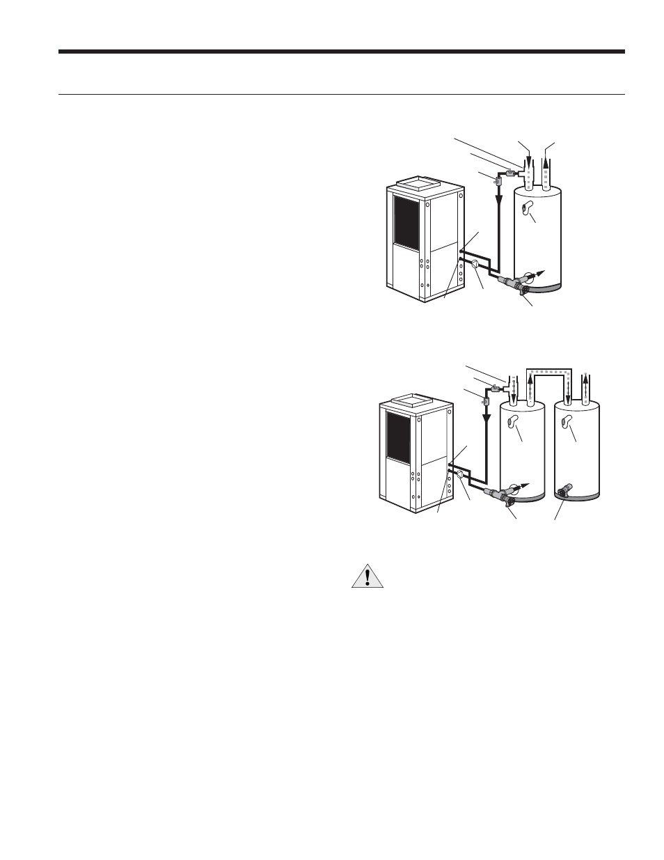
Typical Hot Water Generator Installation
Drain Valve
In
P/T Relief
Valve
Cold
Water In
Hot
Water Out
HWG
Water In
HWG
Water Out
Ball Valve
19.1mm x 19.1mm x 12.7mm Tee
Vent
Field Installed
HWG Pump
Hot Water Generator Connections
CAUTION: Elements will burn out if energized dry.
Hot Water Generator Installation In Preheat Tank
In
Ball Valve
19.1mm x 19.1mm x 12.7mm Tee
Cold
Water In
Hot
Water Out
P/T Relief
Valve
P/T Relief
Valve
HWG
Water In
HWG
Water Out
Drain Valve
Vent
Field Installed
HWG Pump
NOTE: This configuration maximizes hot water generator
capability.
Water Tank Preparation
To install a unit with a hot water generator, follow these
installation guidelines.
1. Turn off the power to the water heater.
2. Attach a water hose to the water tank drain connection
and run the other end of the hose to an open drain
or outdoors.
3. Close the cold water inlet valve to the water heater tank.
4. Drain the tank by opening the valve on the bottom of the
tank, then open the pressure relief valve or hot water faucet.
5. Flush the tank by opening the cold water inlet valve to
the water heater to free the tank of sediments. Close
when draining water is clear.
6. Disconnect the garden hose and remove the drain valve
from the water heater.
7. Refer to Plumbing Installation and Hot Water
Generator Startup.
Plumbing Installation
1. Inspect the dip tube in the water heater cold inlet
for a check valve. If a check valve is present it must
be removed or damage to the hot water generator
circulator will occur.
2. Remove drain valve and fitting.
3. Thread the 19.1 mm NPT x 89 mm brass nipple into the
water heater drain port.
4. Attach the center port of the 19.1 mm FPT tee to the
opposite end of the brass nipple.
5. Attach the 12.7 mm copper to 19.1 mm NPT adaptor to
the side of the tee closest to the unit.
6. Install the drain valve on the tee opposite the adaptor.
7. Run interconnecting tubing from the tee to HWG
water out.
8. Cut the cold water “IN” line going to the water heater.
9. Insert the reducing solder tee in line with cold water
“IN” line as shown.
10. Run interconnecting copper tubing between the unit
DHW water “IN” and the tee (12.7 mm nominal). The
recommended maximum distance is 9.1 m.
11. To prevent air entrapment in the system, install a vent
coupling at the highest point of the interconnecting lines.
12. Insulate all exposed surfaces of both connecting water
lines with 9.5 mm wall closed cell insulation.
NOTE: All plumbing and piping connections must comply
with local plumbing codes.