Vortech H3 I-5 Hummer - 2006-2008 User Manual
Page 9
P/N: 4GN020-010
©2008 Vortech Engineering, LLC
All Rights Reserved, Intl. Copr. Secured
20OCT08 v2.0(4GNv2.0)
1
A. Disconnect the negative battery cable.
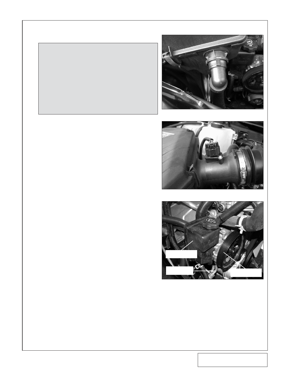
B. Disconnect the evaporative canister vent
hose from the air filter assembly and canister
and set aside. (See Fig. 1-a.)
C. Disconnect the MAF electronics harness con-
nection from the meter. (See Fig. 1-b.)
D. Using a 5/16" nut driver, loosen the hose
clamp securing the inlet duct to the throttle
body.
E.
Remove the two 13mm headed screws
securing the lower portion of the air filter
enclosure to the inner fender. Remove the
two 10mm headed screws securing the inter-
mediate ducting to the cylinder head.
Remove the air filter assembly and set aside.
F.
Remove the MAF electronics from the previ-
ously removed air filter assembly and set
aside to be reused in a later step. (See Fig.
1-b.)
G. Using a 3/8" ratchet, de-tension the accesso-
ry belt tensioner and remove the factory belt.
H. Remove the power steering pulley using the
appropriate pulley puller. Set the pulley aside
to be re-installed in a later step.
I.
Remove the hose from the bottom of the
power steering fluid reservoir. Drain the
power steering fluid into a clean container
and set aside. Once the fluid is drained, dis-
connect the power steering pressure line from
the bottom of the pump. (There may be resid-
ual fluid in this line.) (See Fig. 1-c.)
1.
PREPARATION/REMOVAL
Fig. 1-a
Fig. 1-b
Fig. 1-c
POWER STEERING
RESERVOIR
P/S PRESSURE
LINE
POWER STEERING
PULLEY
NOTE:
1. Locate the vehicles ECU and TCM modules behind the
washer fluid/coolant reservoir assembly passenger side
firewall.
2. Temporarily loosen the washer fluid/coolant reservoir
assembly to gain adequate access to the modules.
3. Unplug the four factory harness connections and
remove the modules from the vehicle.
4. Contact the Vortech Service Department for a Return
Authorization Number. Send both the ECU and TCM
and supplied credit tag to Vortech using the enclosed
shipping materials.