Vortech H3 I-5 Hummer - 2006-2008 User Manual
Page 20
P/N: 4GN020-010
©2008 Vortech Engineering, LLC
All Rights Reserved, Intl. Copr. Secured
20OCT08 v2.0(4GNv2.0)
12
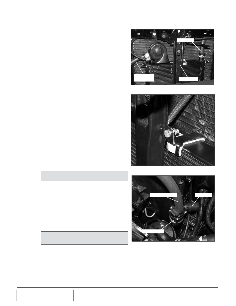
Fig. 7-a
Fig. 7-c
Fig. 7-b
7. ChARGE COOLER INSTALLATION
Refer to Fig.7-h for assistance throughout this
manual.
A. Remove the four screws and two nuts that
secure the grill to the core support.
B. Pull forward on the ends of the grill to release
the push clips holding the grill in place.
C. Locate the Charge Air Cooler assembly
(8N201-320).
D. Install one 1/2"NPT x 3/4" barb 90° brass
elbow and one 1/2"NPT x 3/4" barb straight
fitting into the supplied heat exchanger and
orient as shown
*. (See Fig. 7-h.)
E.
Remove the two 13mm headed screws and
two 10mm headed screws securing the hood
latch support assembly to the core support.
Unclip the wire harness that runs behind the
support. Set the support aside to be rein-
stalled later. (See Fig. 7-a.)
H. Place the supplied piece of 1/8" x 4" tape
foam on the heat exchanger.It may be neces-
sary to trim the tape to fit. Install the upper
heat exchanger bracket and secure using a
1/4-20 x .75" screw, washer and Nyloc nut
provided. (See Fig. 7-b.)
I.
Using the supplied Adel clamps, self-tapping
screws and washers, secure the provided
water pump, to the cooling fan shroud. (See
Fig. 7-c.)
F.
Secure the heat exchanger bracket (8N010-
240) to the heat exchanger using the 1/4-20 x
.75" screws, washers and Nyloc nuts provid-
ed. Loosely install the heat exchanger
assembly into position. (See Fig. 7-a, 7-h.)
G. Reinstall the hood latch support (the heat
exchanger bracket is between the core sup-
port and the hood latch support) secure using
the factory hardware. Feed the sensor leads
through their respective sides and reconnect
to the sensors.
J.
Secure the supplied Ø2.75" X 2" sleeve to
the supercharger discharge using a #44 hose
clamp. (See Fig. 7-d.)
K. Using the Ø3.35" to Ø2.75" reducer elbow,
install the Charge Air Cooler between the pre-
viously installed sleeve and the throttle body.
(See Fig. 7-d.)
NOTE:
Careful not to pinch wires between the
brackets.
NOTE:
Orient the pump discharge so that it points to
the front passenger side of the vehicle.
150° MOLDED
HOSE
Latch Support
90° HOSE
150° HOSE
HOSE FROM CAC
WATER PUMP
*
Use pipe sealant on tapered pipe threads.