Vortech H3 I-5 Hummer - 2006-2008 User Manual
Page 25
P/N: 4GN020-010
©2008 Vortech Engineering, LLC
All Rights Reserved, Intl. Copr. Secured
20OCT08 v2.0(4GNv2.0)
17
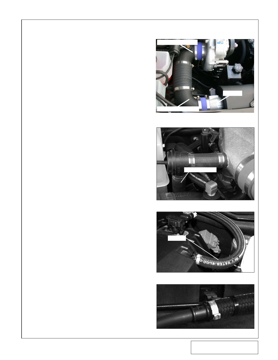
H. Secure the supplied 3.5" x 2" sleeve to the
MAF meter using the supplied #56 hose
clamp. Attach the 3.5" 90°duct with out boss-
es to the previously installed sleeve and
secure using a #56 hose clamp. (See
Fig. 8-d.)
I
.
Locate the 3.5" x 90° duct with bosses and
install the 3/4"NPT x 90° and 3/8"NPT
elbows. Secure the 3.5" x 90° duct to the
supercharger inlet using the Ø3.5 x 2" sleeve
and two #56 hose clamps provided (See Fig.
J.
Connect the two 90° inlet ducts using the
Ø3.5 x 10" flex hose and secure using the
remaining #52 hose clamps provided. (See
Fig. 8-d.)
K. Cut approximately 4" from the long leg of the
supplied Ø1" x 90° molded hose. Set the cut
piece aside to be used later. Connect the
short leg of the supplied Ø1" x 90° molded
hose to the previously installed 1" plastic 90°
elbow in the inlet duct. Orientate so that the
open end of the hose is pointing up. Secure
using the supplied #16 hose clamp. (See
Fig. 8-e.)
L.
Install the by-pass valve discharge port into
the open end (cut end) of the Ø1" x 90° mold-
ed hose, and secure using one of the #16
hose clamps provided. (See Fig. 8-e.)
M. Locate the piece of hose previously cut from
the Ø1" x 90° molded hose. Trim this hose to
approximately three inches. Connect the by-
pass valve inlet port to the Ø1" bung on
charge air cooler using the 3" piece of hose.
Secure using the remaining #16 hose clamps
provided. (See Fig. 8-e.)
N. Locate the 1/2" vacuum port on the drivers
side of the intake manifold. Remove the rub-
ber cap from the port. Using the supplied
1/2" I.D. vacuum line attach the 1/2" x 1/4"
plastic reducer coupling provided. Connect
the 1/4" x 5/32" brass reducer coupling to the
previously installed 1/2" x 1/4" plastic reducer
coupling using the 1/4" I.D. vacuum line pro-
vided. (See Figs. 8-f, 8-g.)
O. Attach a length of 5/32" vacuum hose to the
bypass valve. Route the open end of the
hose to the 1/4" x 5/32" brass reducer cou-
pling previously installed and connect.
P.
Reinstall the grill in the reverse order
removed, using the factory hardware.
Fig. 8-e
Fig. 8-f
Fig. 8-g
Fig. 8-d
8. AIR INLET INSTALLATION, cont’d
1/2" LINE
3.5” 90° Elbow w/ bosses
MAF Meter
3.5” 90° Elbow w/o bosses
90° MOLDED HOSE