Removing and installing the scsi i/o module – StorCase Technology 4-Bay Desktop SCSI Ultra320 User Manual
Page 21
InfoStation 4-Bay User's Guide - Rev. C01
StorCase Technology, Inc.
Installation
13
NOTES:
Each bay has a factory default SCSI ID as follows:
Bay 1 = SCSI ID 0
Bay 3 = SCSI ID 2
Bay 2 = SCSI ID 1
Bay 4 = SCSI ID 3
Factory default SAF-TE Processor Board SCSI ID (if factory-installed) is
15.
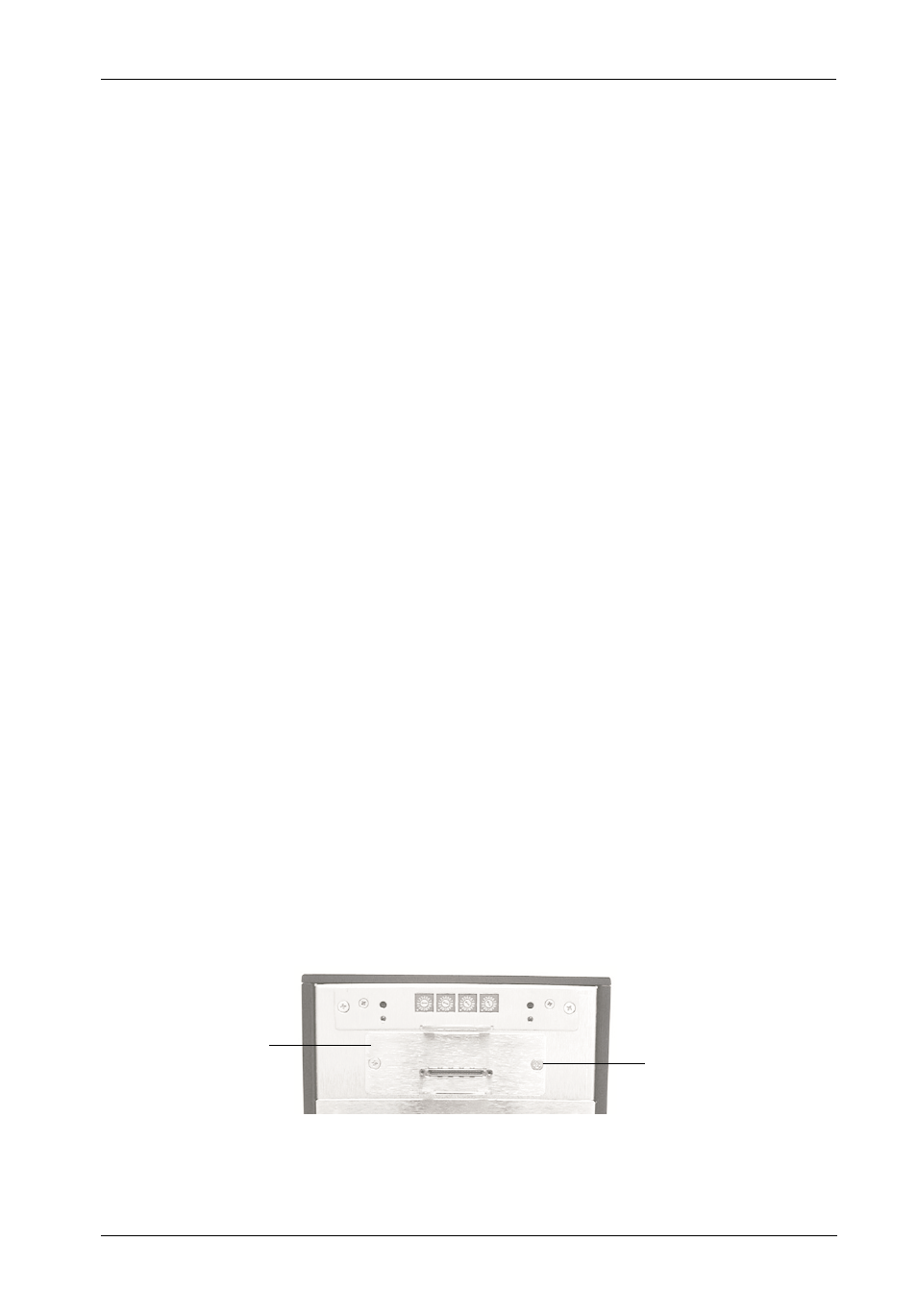
Figure 9: Removing and Installing the SCSI I/O Module
Removing and Installing the SCSI I/O Module
(Procedure and information below applies to both the SCSI I/O Module and the optional SCSI
I/O Repeater Modules)
CAUTION:
Remove ALL power from the InfoStation before removing and/or installing
the SCSI I/O module. The SCSI I/O module contains NO USER SERVICE
ABLE PARTS inside the unit. Refer ALL servicing to qualified service
personnel!
VHDCI connectors are easily damaged by improper handling. Visually
inspect each connector for bent contacts and carefully align prior to
insertion.
NOTES:
The SCSI I/O module is NOT hot-swappable! Remove ALL power to
chassis before removing and installing the SCSI I/O module.
An optional SCSI I/O Repeater Module is available as an upgrade. Contact
StorCase for further information.
1.
Unplug the InfoStation and verify that ALL cables have been disconnected.
2.
Place the InfoStation on a soft clean surface to protect finish of the chassis.
3.
Loosen and remove the two (2) #6-32 Phillips Flat Hd. screws securing the SCSI
I/O module to the InfoStation chassis (Figure 9).
4.
Remove the SCSI I/O module by grasping handle and pulling out from chassis.
5.
To install SCSI I/O module, simply reverse above mentioned steps.
I/O Module
#6-32 Phillips
F.H. Screw
(2 Total)