Receiving frame rear panel – StorCase Technology DE110 User Manual
Page 17
10
Introduction
StorCase Technology, Inc.
Encrypted DE110 User's Guide - Rev. A01
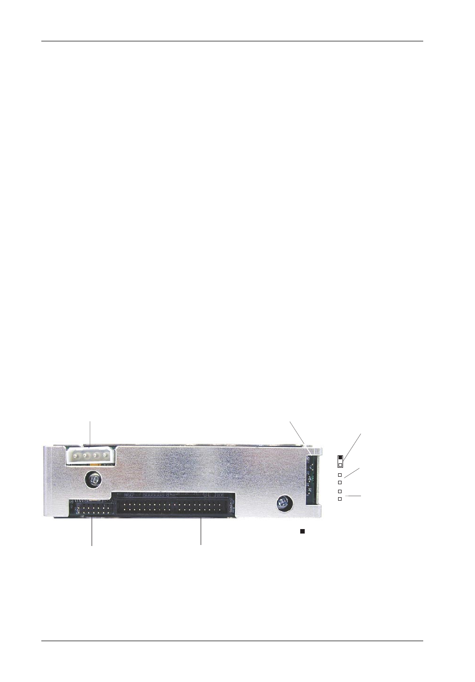
Figure 6: Receiving Frame Motherboard
(Rear View)
Receiving Frame Rear Panel
I/O Connector (JP1) - The input/output connector provides a standard interface for all
IDE signals.
DC Power Connector (P1) - A standard 4-pin DC power connector is used to accept
DC power.
Option Pins (W1)
Master/Slave Selection Jumper (ID0 & ID1) - Master Drive designation (jumper is
factory-installed on ID0). Change jumper position to Pins 3 & 4 (ID1) for Slave Drive
designation.
Forces Master/Slave Drive configuration on the receiving frame, if jumper option on the
drive itself is configured for Cable Selection (recommended configuration). Refer to
page 10 for further information.
If using the Drive Select Method, this option is instead used to configure the unit ID display
only (refer to page 10 for further information).
Reserved - These pins are reserved for factory use only.
Factory Reserved Pins - These pins are reserved for factory use only - Do not install
jumper under any circumstances!
DC Power
Connector
Option Pin
Connector
I/O
Connector
Factory-Reserved Pins
(No Jumper Installed)
1
2
Master Drive
Select (ID0)
(Factory-Installed
Jumper)
= Pin 1
Slave Drive
Select (ID1)
4
3
6
5
Reserved