Receiving frame front panel – StorCase Technology DE110 User Manual
Page 12
Introduction
5
Encrypted DE110 User's Guide - Rev. A01
StorCase Technology, Inc.
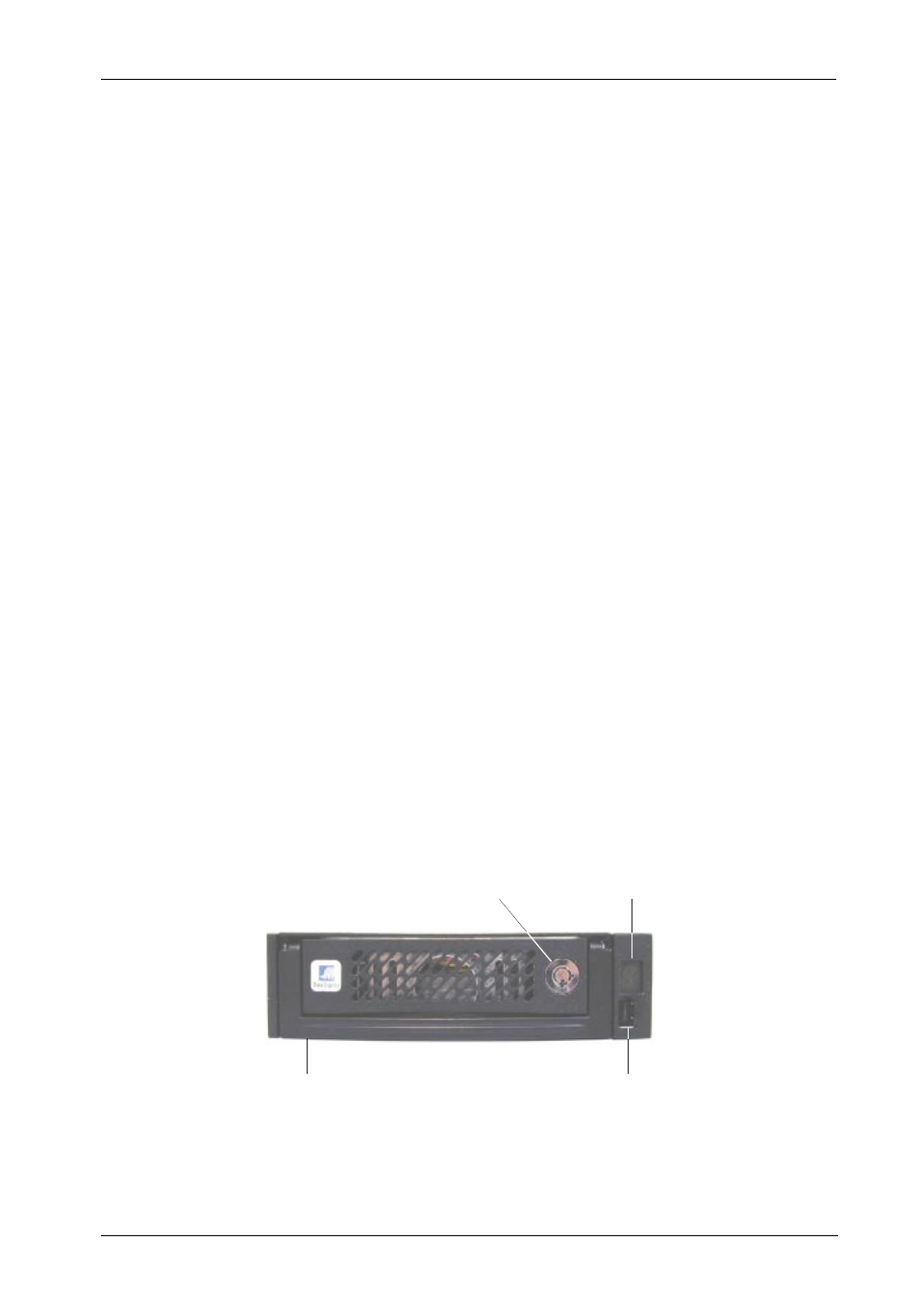
Figure 3A: Receiving Frame Front Panel
Receiving Frame Front Panel
Key Lock/Drive Power Switch (Figure 3) - Performs three functions. The key
switch assures proper seating of the drive carrier within the receiving frame, turns
power to the drive carrier ON and OFF, and prevents unauthorized removal or
installation of the carrier. For the computer to access data on the disk drive, the key
must be turned counterclockwise to the locked position.
Unit ID Number Indicator (Figures 3A & 3B) - This LED displays the physical
address of the DE110 device carrier if the carrier is Installed and Locked in the
receiving frame or if the carrier is removed from the receiving frame. If the carrier
is Installed but not Locked in the receiving frame, a "u" will be displayed to indicate
an unlocked condition.
The Activity Indicator (Figures 3A & 3B) - A small dot next to the unit ID number
illuminates to indicate when the host computer is accessing the data on the DE110
carrier. This dot will flash during communication with the host computer.
Electronic Security Key Slot (Figure 3A) - A 64-bit (blue) or 128-bit (black)
electronic security key (provided) is required to authenticate cryptographic opera-
tion. Security key must be inserted before powering ON the host system (when in
Encryption/Decryption mode). Security key is not required when operating in Bypass
mode.
WARNING:
DO NOT lose your electronic security keys! StorCase does not pro-
vide duplicate keys, and assumes no responsibility for lost data re-
sulting from lost or stolen keys.
NOTE:
Electronic security key must be inserted before powering ON the host
system (when in Encryption/Decryption mode). Security key is not re-
quired when operating in Bypass mode.
Carrier
Handle
Key Lock/
Power Switch
Unit ID Number/
Activity Indicator
Electronic Security
Key Slot