Receiving frame rear panel – StorCase Technology DE100i-A66 User Manual
Page 12
DE100i-A66 User's Guide - Rev. A00
StorCase Technology Inc.
Introduction
5
Receiving Frame Rear Panel
DC Power Connector (J3): The DE100i-A66 uses a standard 4-pin DC Power
Connector to accept DC power.
I/O Connector (J2): The input/output connector provides a standard interface for
all IDE signals. See Table 3 for J2 pin assignments.
Master/Slave Selection Jumper (J5): Master Drive configuration (default).
Forces master drive configuration on receiving frame. Change jumper to set slave
drive configuration. Refer to Table 2 for further information.
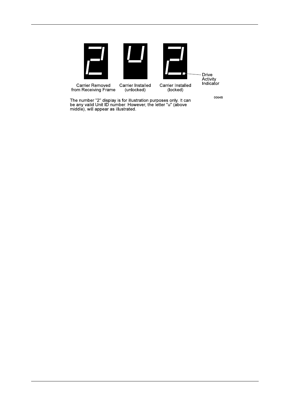
Device Spin Down/Up Timer Jumper (J6): Jumper installed (factory default)
enables device spin down/up visual indicator. Receiving frame unit number display
(Figure 4) will flash to indicate device spin down/up.
Figure 4: Receiving Frame Unit Number and Activity Display
- DE100i-SW (35 pages)
- DE50 (33 pages)
- DE50 (27 pages)
- DE110 (33 pages)
- DE110 (2 pages)
- DE110 (31 pages)
- DE110 (27 pages)
- DX115 (25 pages)
- DE75i-A (31 pages)
- DE75i-A66 (29 pages)
- DE75i-A100 (31 pages)
- SATA DE75 (28 pages)
- DE75i-S (31 pages)
- DE75i-SW (33 pages)
- DE75i-SWC (33 pages)
- DE75i-SW160 (29 pages)
- S20A114 (29 pages)
- DE75i-SWC160 (29 pages)
- DE90i-A (29 pages)
- DE90i-A66 (23 pages)
- DE90i-A100 (23 pages)
- DE90i-S (25 pages)
- DE100i-A (33 pages)
- DE100i-A100 (29 pages)
- DE100i-CSWTN (2 pages)
- DE100i-S (39 pages)
- DE100i-SWD (33 pages)
- DE100i-SWU2 (37 pages)
- DE100i-SWCU2 (33 pages)
- DE100i-SWU2X (35 pages)
- DE100i-SW160 (35 pages)
- S20A102 (33 pages)
- DE100i-SWC160 (39 pages)
- Ultra320 DE100 (31 pages)
- DE110 (29 pages)
- DE110 (27 pages)
- DE110 (31 pages)
- DE150i-SWC (33 pages)
- DE200i-S (33 pages)
- DE200i-CSWTN (2 pages)
- DE200i-SW (35 pages)
- DE200i-SWU2 (37 pages)
- DE200i-SWCU2 (35 pages)
- S20A108 (33 pages)