Receiving frame front panel – StorCase Technology DE100i-A66 User Manual
Page 11
StorCase Technology Inc.
DE100i-A66 User's Guide - Rev. A00
4
Introduction
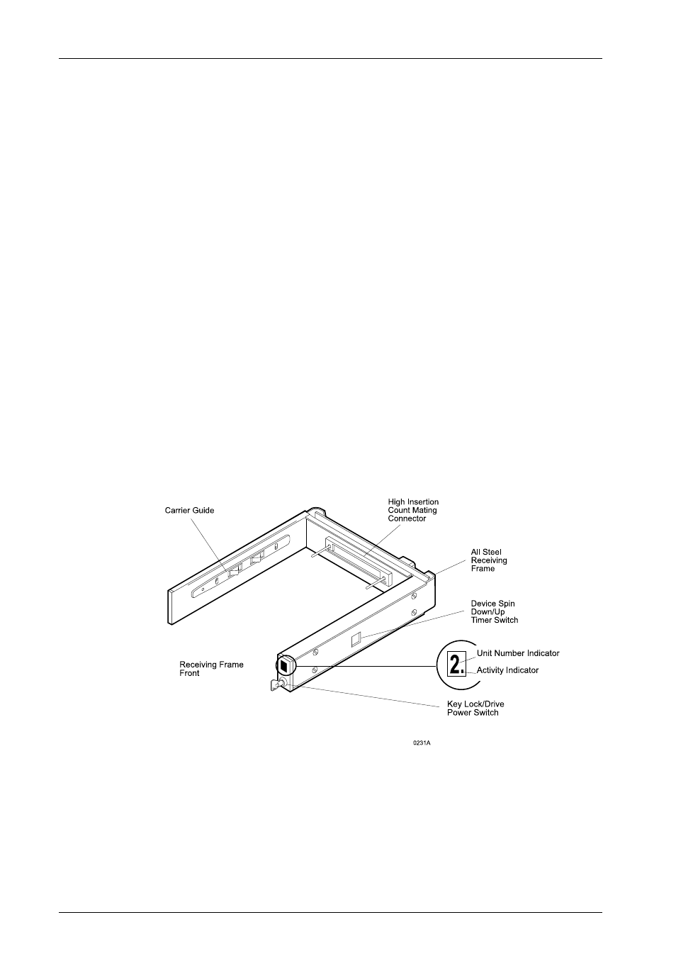
Receiving Frame Front Panel
The Key Lock/Drive Power Switch performs three (3) functions. The key lock
assures proper seating of the drive carrier within the receiving frame, turns power
to the drive carrier on and off, and prevents unauthorized removal or installation of
the carrier. For the computer to access data on the DE100i-A66 drive, the key must
be turned counterclockwise to the locked position.
The Unit Number Display (Figure 4) shows the physical address of the DE100i-
A66 drive carrier when the carrier is Installed and Locked in the receiving frame
or Removed from the receiving frame. If the drive carrier is Installed but Not Locked,
a "u" will be displayed. The unit number is selected by means of the unit select switch
located inside the receiving frame using a special alignment tool supplied with the
DE100i-A66. This procedure is explained later during the installation process.
The Activity Indicator is a small dot next to the Unit Number which flashes when
the host computer is accessing data on the DE100i-A66 carrier. Refer to "Drive
Activity Indicator Connector (J5)" on page 8 for further information.
Device Spin Down/Up Timer may be disabled by removing Jumper J6 P1-P2
(Figure 5). This feature allows the receiving frame unit number display to provide
a visual indication of drive spin down/up activity.
Figure 3: Receiving Frame Front Panel