Installation – StorCase Technology DE75i-A100 User Manual
Page 17
10
Installation
StorCase Technology, Inc.
DE75i-A100 User's Guide - Rev. D02
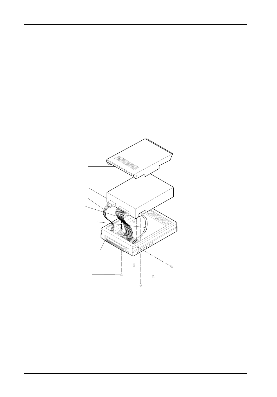
4.
Carefully insert the drive into the drive carrier at an angle, cable-end first. Make
sure none of the cables are pinched. Lower the front of the drive carefully into
place. Fasten the drive into the carrier with four of the eight screws provided as
shown in Figure 8.
5.
Install the provided drive cover.
Figure 8: Drive Installation Assembly
Installation
1.
Attach the I/O cable on the drive carrier circuit board to the drive (Figure 8).
2.
Attach the DC power cable on the drive carrier circuit board to the drive (Figure 8).
If you are installing only one drive carrier, skip to Step 4.
3.
For Method 2 Users:
If a Master/Slave cable was fabricated as outlined in the previous section, install
it now between the appropriate drive pins and connector JP3 on the drive carrier
circuit board (refer to Figure 6 for examples of Ultra ATA133 Master/Slave drive
connections). Also refer to the drive manufacturer's documentation for more spe-
cific information.
Drive Carrier
Drive
(Not Included)
Power Cable
I/O Cable
Drive Mounting
Screws (4ea)
Phillips # 6-32 x
3/16 Flat HD
Fabricated Cable
(Used for
Master/Slave Drive
Connection, not
included. See
Installation section
for further
0607
Protective
Drive
Cover
(Provided)
Drive Cover
Screws (2 plcs)
# 6-32 x 3/16
Flat HD