StorCase Technology DE75i-A100 User Manual
Page 15
8
Installation
StorCase Technology, Inc.
DE75i-A100 User's Guide - Rev. D02
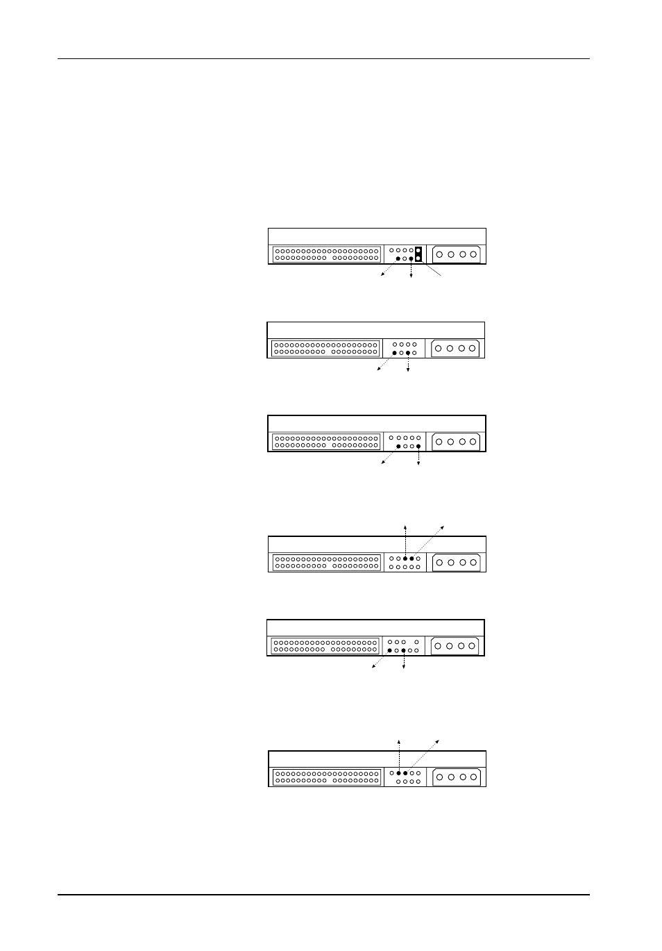
Figure 6: Examples of Ultra ATA Master/Slave Drive Connections
IBM
ATA66/100 Drive
JP3
Pin 3
JP3
Pin 2
Jumper
Installed
JP3
Pin 3
JP3
Pin 2
Seagate
ATA66/100 Drive
JP3
Pin 3
JP3
Pin 2
Western Digital
ATA66 Drive
JP3
Pin 3
JP3
Pin 2
Maxtor
ATA66 Drive
Maxtor
ATA100 Drive
JP3
Pin 3
JP3
Pin 2
112a
JP3
Pin 3
JP3
Pin 2
Western Digital
ATA100 Drive
Examples of Ultra ATA133 drive pin positions are shown in Figure 6. Remove and save all
jumpers. Install a cable wire (not provided) connecting the appropriate drive pins to the
appropriate JP3 pins as shown in Figure 6. Installation of a jumper may also be necessary,
depending on model.
NOTE:
Pin assignments may vary depending on model, refer to the drive manu-
facturer's documentation for specific information regarding your drive.
- DE100i-SW (35 pages)
- DE110 (2 pages)
- DE110 (31 pages)
- DE110 (27 pages)
- DE50 (33 pages)
- DE50 (27 pages)
- DE110 (33 pages)
- DX115 (25 pages)
- DE75i-A (31 pages)
- DE75i-A66 (29 pages)
- SATA DE75 (28 pages)
- DE75i-S (31 pages)
- DE75i-SW (33 pages)
- DE75i-SWC (33 pages)
- DE75i-SW160 (29 pages)
- S20A114 (29 pages)
- DE75i-SWC160 (29 pages)
- DE90i-A (29 pages)
- DE90i-A66 (23 pages)
- DE90i-A100 (23 pages)
- DE90i-S (25 pages)
- DE100i-A (33 pages)
- DE100i-A66 (29 pages)
- DE100i-A100 (29 pages)
- DE100i-CSWTN (2 pages)
- DE100i-S (39 pages)
- DE100i-SWD (33 pages)
- DE100i-SWU2 (37 pages)
- DE100i-SWCU2 (33 pages)
- DE100i-SWU2X (35 pages)
- DE100i-SW160 (35 pages)
- S20A102 (33 pages)
- DE100i-SWC160 (39 pages)
- Ultra320 DE100 (31 pages)
- DE110 (27 pages)
- DE110 (31 pages)
- DE110 (29 pages)
- DE150i-SWC (33 pages)
- DE200i-S (33 pages)
- DE200i-CSWTN (2 pages)
- DE200i-SW (35 pages)
- DE200i-SWU2 (37 pages)
- DE200i-SWCU2 (35 pages)
- S20A108 (33 pages)