StorCase Technology DE75i-A100 User Manual
Page 16
DE75i-A100 User's Guide - Rev. D02
StorCase Technology, Inc.
Installation
9
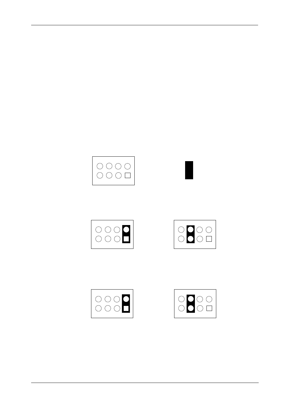
Configuring the Receiving Frame Motherboard (JP4)
Once the Master/Slave configuration on the drive carrier circuit board is complete, the JP4
jumper(s) on the receiving frame motherboard must be configured as shown in Figure 7.
The appropriate jumper setting must still be configured on JP6 (ID0 & ID1) located on the
receiving frame motherboard (Figure 4). For Master setting, install jumper on ID0 (Pins 1 & 2).
For slave setting, install jumper on ID1 (Pins 3 & 4).
Figure 7: Typical Receiving Frame JP4 Master/Slave Jumper Settings
Single (1) Western Digital ATA100 Drive:
8
7
5
6
3
4
1
2
Dual (2) Western Digital ATA100 Drives:
112b
8
7
5
6
3
4
1
2
Other Drives:
Master
(or Single)
8
7
5
6
3
4
1
2
Slave
8
7
5
6
3
4
1
2
Master
8
7
5
6
3
4
1
2
Slave
= Jumper Installed
- DE100i-SW (35 pages)
- DE110 (2 pages)
- DE110 (31 pages)
- DE110 (27 pages)
- DE50 (33 pages)
- DE50 (27 pages)
- DE110 (33 pages)
- DX115 (25 pages)
- DE75i-A (31 pages)
- DE75i-A66 (29 pages)
- SATA DE75 (28 pages)
- DE75i-S (31 pages)
- DE75i-SW (33 pages)
- DE75i-SWC (33 pages)
- DE75i-SW160 (29 pages)
- S20A114 (29 pages)
- DE75i-SWC160 (29 pages)
- DE90i-A (29 pages)
- DE90i-A66 (23 pages)
- DE90i-A100 (23 pages)
- DE90i-S (25 pages)
- DE100i-A (33 pages)
- DE100i-A66 (29 pages)
- DE100i-A100 (29 pages)
- DE100i-CSWTN (2 pages)
- DE100i-S (39 pages)
- DE100i-SWD (33 pages)
- DE100i-SWU2 (37 pages)
- DE100i-SWCU2 (33 pages)
- DE100i-SWU2X (35 pages)
- DE100i-SW160 (35 pages)
- S20A102 (33 pages)
- DE100i-SWC160 (39 pages)
- Ultra320 DE100 (31 pages)
- DE110 (27 pages)
- DE110 (31 pages)
- DE110 (29 pages)
- DE150i-SWC (33 pages)
- DE200i-S (33 pages)
- DE200i-CSWTN (2 pages)
- DE200i-SW (35 pages)
- DE200i-SWU2 (37 pages)
- DE200i-SWCU2 (35 pages)
- S20A108 (33 pages)