Method 2 – StorCase Technology DE75i-A100 User Manual
Page 14
DE75i-A100 User's Guide - Rev. D02
StorCase Technology, Inc.
Installation
7
Method 2
- Using the hard-wire connector JP3 on the drive carrier circuit board to allow
drive carrier interchangeability between Master/Slave configured receiving
frames
NOTE:
Cable wire not included.
For drive carrier interchangeability between Master/Slave configured receiving frames,it is
necessary to set the Master/Slave drive selection by both a hard-wire connection (cable wires
not included) between the drive and the drive carrier circuit board.
This method requires the fabrication of a cable wire (not provided). Refer to the following
sections to configure the drive carrier circuit board and jumper (JP4) located on the receiving
frame (both required for Method 2).
Configuring the Drive Carrier Circuit Board
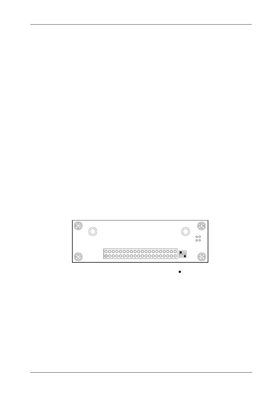
The appropriate pins on the drive must be connected to JP3 on the carrier board. These
connections are required to set the Master/Slave configurations of the installed drive. Figure
5 illustrates the Drive Carrier Circuit Board.
When configuring the dual drives for interchangeable Master/Slave assignment, it is necessary
to emulate the Master and Slave drive jumpers and the specific drive's signal polarity definition
of Master and Slave.
Figure 5: DE75i-A100 Drive Carrier Circuit Board
112
JP3
= Pin 1
I/O Connector (J2)
RB
YB
The JP3 connector has 3 pins:
Pin 1
Not used.
Pin 2
Connects to the Slave/Slave Present signal of the drive. This signal indicates
whether a Slave D: drive is present or not.
Pin 3
Connects to the Master signal of the disk drive. This signal indicates that this
is the Master C: drive.