Receiving frame rear panel – StorCase Technology DE75i-A100 User Manual
Page 12
DE75i-A100 User's Guide - Rev. D02
StorCase Technology, Inc.
Introduction
5
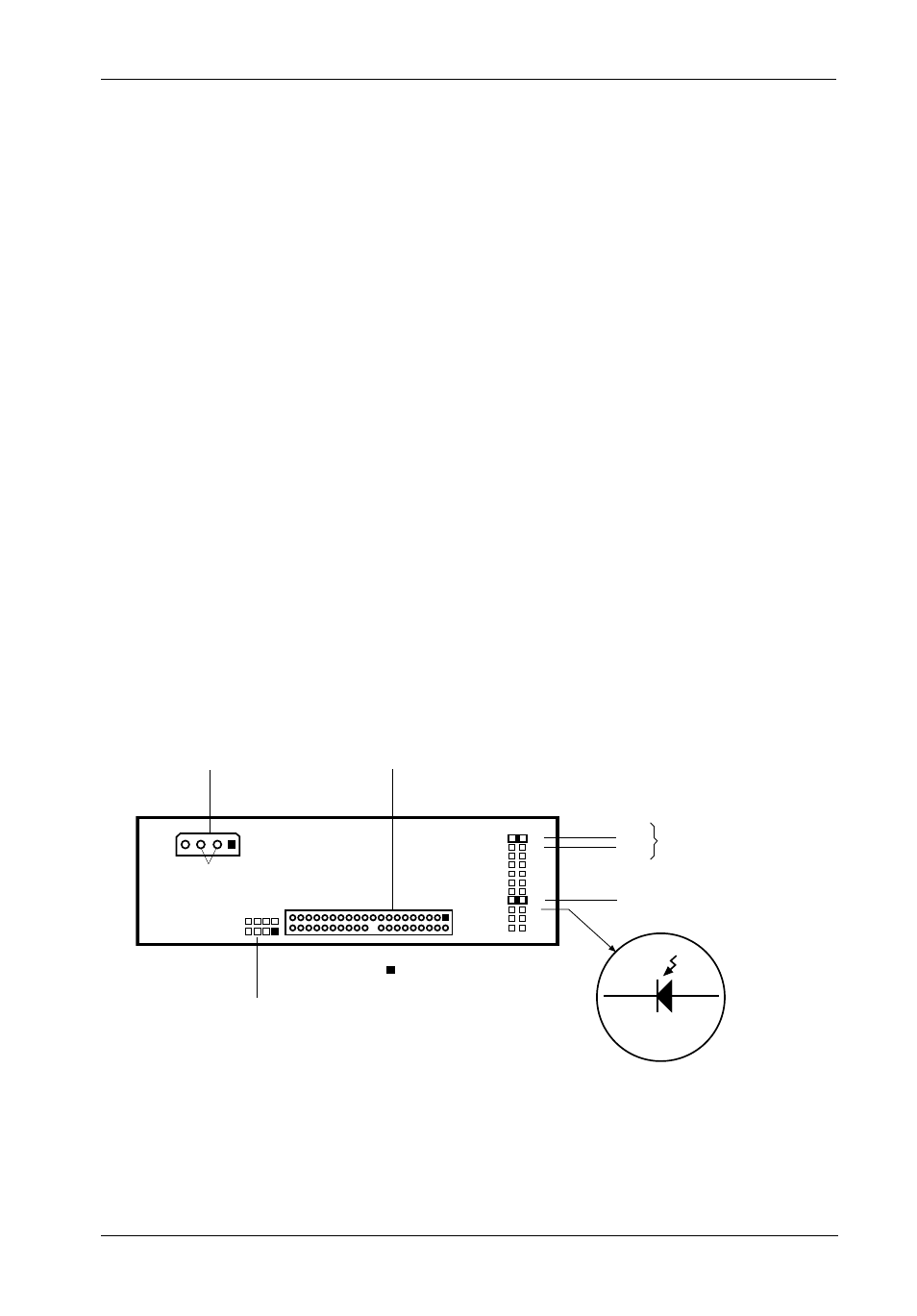
Figure 4: Receiving Frame Rear Panel (Motherboard)
Receiving Frame Rear Panel
(Figure 4)
DC Power Connector (P1): The Data Express uses a standard 4-pin DC Power
Connector to accept DC power.
I/O Connector (JP1): The input/output connector provides a standard interface
for all IDE signals. See Table 1 for JP1 pin assignments.
JP6 Header:
Master/Slave Setting (JP6 ID0 & ID1):
ID0:
Jumper installed on Pins 1 & 2 (Factory Default) for Master
configuration.
ID1:
Jumper installed on Pins 3 & 4 for Slave configuration.
Remote Drive Activity (JP6 RLED): Pins 17 & 18 are used for remote drive activity.
Jumper (JP6 DDA): Factory-installed on Pins 15 & 16 - Do not remove!
JP4 Option: Refer to "Method 2" in the Installation section for further information.
DC Power
Connector
P1
+5
+12
GND
1
2
21
22
I/O Connector
JP1
0603a
Anode
Cathode
P17
P18
JP6
Remote Activity
LED
18
17
JP4
4
3
ID0
ID1
Master/Slave
Configuration
Jumper (Do Not Remove!)
= Pin 1
16
15
JP4 Option