Receiving frame front panel – StorCase Technology DE75i-A100 User Manual
Page 11
StorCase Technology, Inc.
DE75i-A100 User's Guide - Rev. D02
4
Introduction
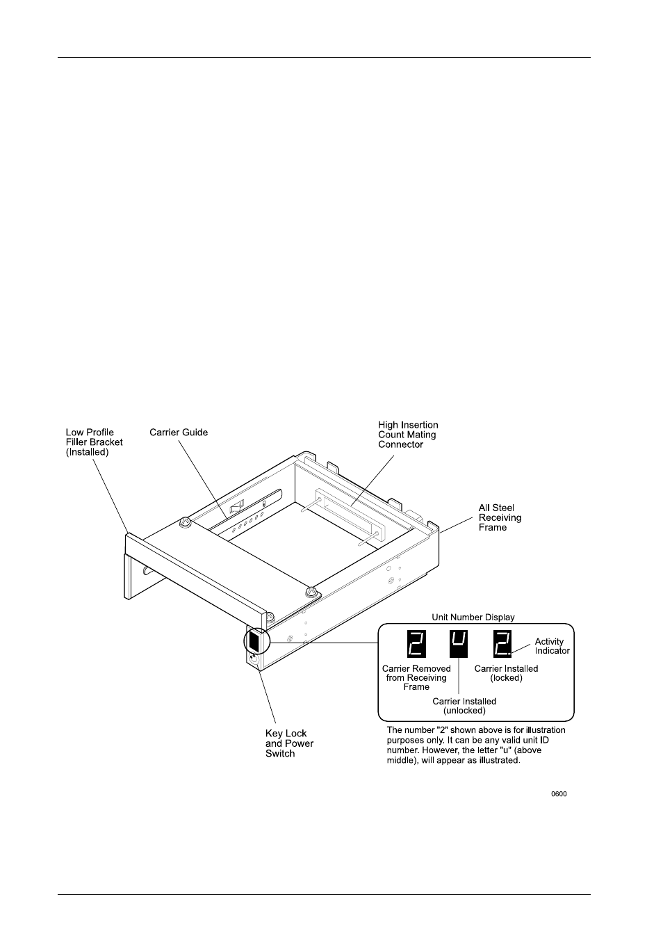
Figure 3: Receiving Frame Front Panel
Receiving Frame Front Panel
(Figure 3)
The Key Lock/Drive Power Switch performs three functions. The key lock
assures proper seating of the drive carrier within the receiving frame, turns power
to the drive carrier on and off, and prevents unauthorized removal or installation of
the carrier. For the computer to access data on the DE75i-A100 drive, the key must
be turned counterclockwise to the locked position.
The Unit ID Number Indicator displays the physical address of the DE75i-A100
drive carrier when the carrier is Installed and Locked in the receiving frame or
Removed from the receiving frame. If the drive carrier is Installed but Not Locked
, a "u" will be displayed. The unit ID number is selected by means of the unit ID select
switch located inside the receiving frame using a special alignment tool supplied with
the DE75i-A100. This procedure is explained later during the installation process.
The Activity Indicator is a small dot next to the Unit ID Number which illuminates
to show when the host computer is accessing the data on the DE75i-A100 carrier.