Spectrum Controls 1756sc-CTR8 User Manual
Page 19
2. Key the RTB in positions that correspond to unkeyed module
positions. Insert the wedge-shaped tab on the RTB with the rounded
edge first. Push the tab onto the RTB until it stops.
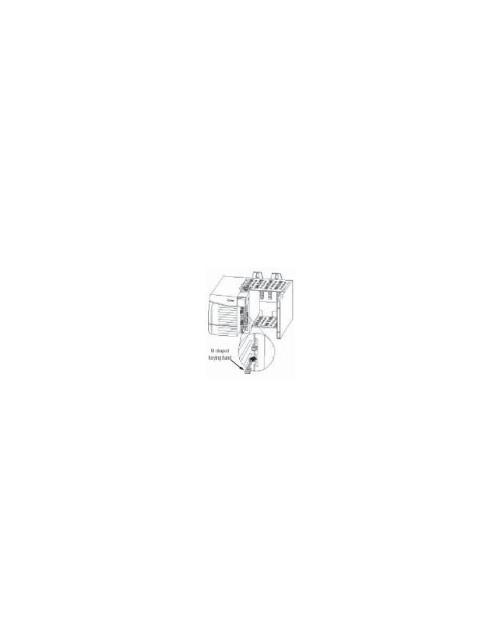
Keying the Removable Terminal Block
Key the RTB to prevent inadvertently connecting the incorrect RTB to
your module.
When the RTB mounts onto the module, keying positions will match up.
For example, if you place a U-shaped keying band in position #4 on the
module, you cannot place a wedge-shaped tab in #4 on the RTB or your
RTB will not mount on the module.
We recommend that you use a unique keying pattern for each slot in the
chassis.
1. Insert the U-shaped band with the longer side near the terminals. Push
the band onto the module until it snaps into place.
Figure 2.2. Terminal block diagram with keying
Wiring Your Module
Follow these guidelines to wire your input signal cables:
•
Power, input, and output (I/O) wiring must be in accordance with
Class 1, Division 2 wiring methods [Article 501-4(b) of the National
Electrical Code, NFPA 70] and in accordance with the authority having
jurisdiction.
•
Peripheral equipment must be suitable for the location in which it is
used.
•
Route the field wiring away from any other wiring and as far as
possible from sources of electrical noise, such as motors, transformers,
contactors, and ac devices. As a general rule, allow at least 6 in. (about
15.2 cm) of separation for every 120 V of power.
•
Routing the field wiring in a grounded conduit can reduce electrical
noise further.