SOR Vane Operated Flow Switch User Manual
Page 3
Form 588 (04.13) ©SOR Inc.
3/4
Process Connection
Integrally mounted controls should
be mounted with the vessel flange
or nozzle within 3° of the vertical or
horizontal centerline of the vessel,
as applicable.
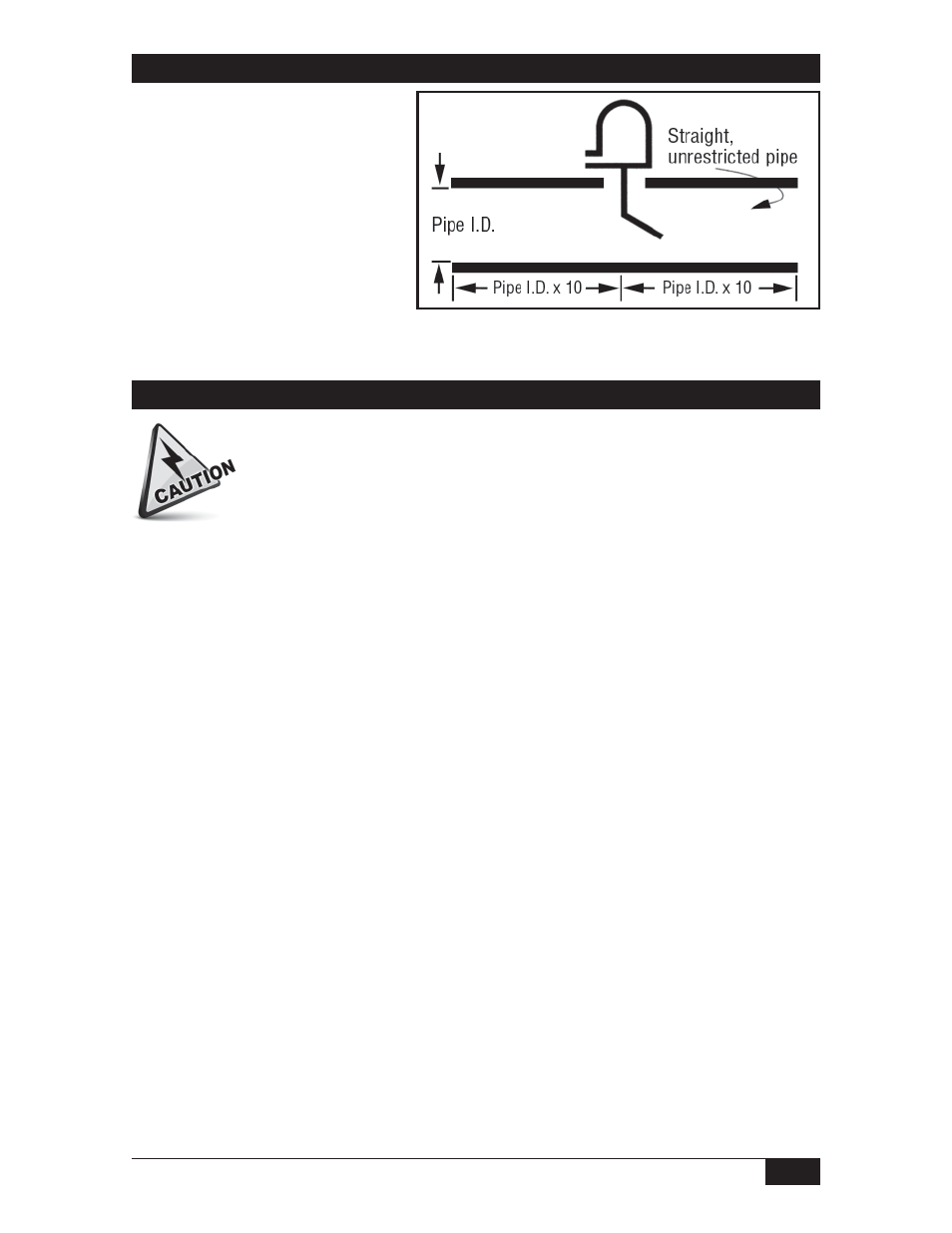
Control should be mounted with
ten diameters (pipe ID x 10) length
straight, unrestricted pipe on
both sides.
Insulation of the control is not recommended.
Ensure that wiring conforms to all applicable local and national electrical codes and install
unit(s) according to relevant national and local safety codes.
Switch housing conduit connections can be rotated 360° by loosening the set screw
located under the housing base. Do not attempt to rotate the housing without loosening set
screw. Retighten the set screw after adjusting the housing.
Care must be taken in positioning the incoming wiring to ensure clearance between the
wiring and switch housing. Switch wiring should be brought through the conduit
connection, under the baffle plate, wrapped around the sealing tube and brought up to
the proper terminal. All excess wire should be cut off prior to stripping the wire to avoid
interference with the action of the switch mechanism or housing cover.
All housings must be properly “sealed” at the conduit connection to maintain the
NEMA classification.
Check housing-to-base fit to ensure the gaskets are sealing properly.
Electrical Connection
Electrical power must be disconnected from explosion proof models before
the cover is removed. Failure to do so could result in severe personal injury
or substantial property damage.