Threaded connection shown – SOR Vane Operated Flow Switch User Manual
Page 2
2/4
Form 588 (04.13) ©SOR Inc.
Dimensions are
for reference only.
Contact the factory
for certified drawings
for a particular
model number.
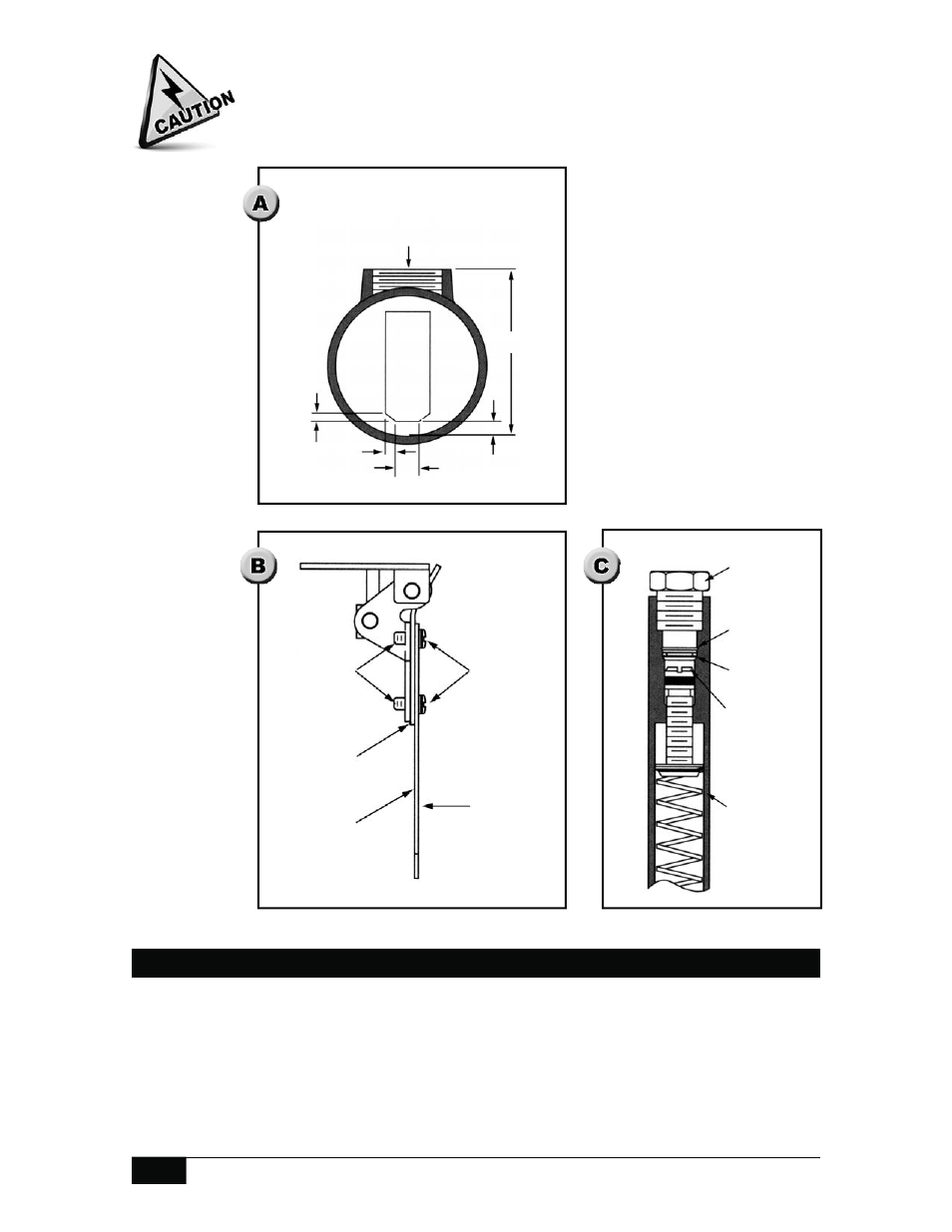
The safety retaining ring prevents accidental removal of the switch
adjustment screw. Do not use force to unscrew the adjustment screw
since the sudden release of the adjustment screw under pressure could
cause injury to the person adjusting the switch.
2” NPT
Conn.
1/4”
1/2”
3/4”
3/16” Min.
Clearance
C
Threaded connection shown
Deform
screw threads
from backside
Small vane
Large vane
Tighten firmly
Flow
Hex Plug
Safety
Retaining Ring
Washer
Switch
Adjustment
Screw
Enclosing
Tube
Safety Integrity Level (SIL) Installation Requirements
The SOR pressure switches have been evaluated as Type-A safety related hardware.
To meet the necessary installation requirements for the SIL system, the following
information must be utilized:
Proof Test Interval shall be one year.
Units may only be installed for use in Low Demand Mode.
Products have a HFT (Hardware Fault Tolerance) of 0, and were evaluated in a
1oo1 (one out of one) configuration.
Form 1538 (03.12) ©2012 SOR Inc.
- Adjustable Dead Band Explosion Proof Pressure Switch (4 pages)
- 805QS Pressure Switch-Transmitter (8 pages)
- 805PT Pressure Transmitter (12 pages)
- Big Hermet Explosion Proof, Hermetically Sealed, Pressure Switch (8 pages)
- Bourdon Tube Explosion Proof Pressure Switch (4 pages)
- Dual Hi-Lo Explosion Proof Sealed Pressure Switch (4 pages)
- Explosion Proof (8 pages)
- Explosion Proof (4 pages)
- Explosion Proof Pressure Switch UL/CSA/ATEX (8 pages)
- Mini-Hermet (8 pages)
- Mini-Hermet (4 pages)
- Sub Mini Hermet (4 pages)
- Omni Weatherproof Pressure Switch (4 pages)
- Weatherproof Pressure Switch (4 pages)
- Weatherproof Pressure Switch (2 pages)
- 805PT Pressure Transmitter (8 pages)
- 815DT Smart (24 pages)
- 815PT Smart Pressure Transmitter (24 pages)
- 534CR Pressure Transmitter (8 pages)
- 534HS Two-Wire Pressure Transmitters (12 pages)
- 536CR Low Power Pressure Transmitters (8 pages)
- 536HS Low Power Pressure Transmitters (8 pages)
- 510IM Immersible Transmitter (4 pages)
- 503FR Fixed Range Pressure Transmitter (4 pages)
- 101/121 Differential Pressure Switches (12 pages)
- Dual Opposed Diaphragm (12 pages)
- High Static Operation (8 pages)
- High Static Operation (12 pages)
- Low Pressure Switch Low Range Series 20 (8 pages)
- Low Range (4 pages)
- Single Diaphragm (4 pages)
- Big Hermet (12 pages)
- Direct or Remote Mount Explosion Proof UL/CSA/ATEX (8 pages)
- Side Mounted Level Switches (16 pages)
- Flanged Level Switches (4 pages)
- Sealed Level Switches (8 pages)
- 1510 Side Mounted Level Switch (8 pages)
- 1520 Electric Flow Switch (8 pages)
- 1530 Pneumatic Level Switch (4 pages)
- 1540 Side Mounted Non-Bleed Pneumatic Level Switch (4 pages)
- 1550 Top Mounted Level Switch (8 pages)
- 1710 Compact Level Switch (8 pages)
- Multi Point RF Level Switch (36 pages)
- Single Point RF Level Switch (12 pages)
- Single Point RF Level Switch (16 pages)