Dimensions, Replacement switch assemblies – SOR 1710 Compact Level Switch User Manual
Page 4
4/8
Form 916 (03.14) ©SOR Inc.
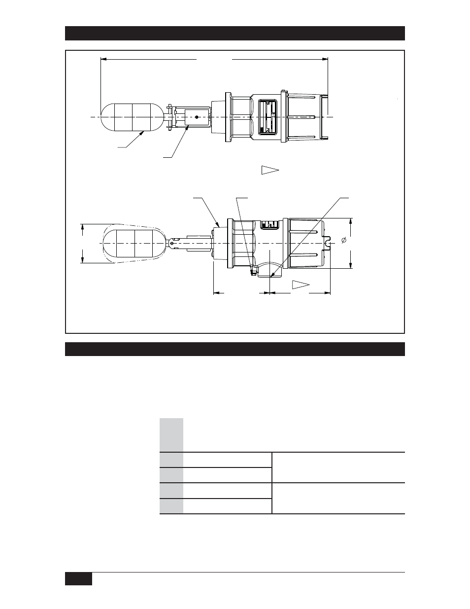
Dimensions
Linear = mm/inches
Drawing 0390777
Dimensions are for reference only. Contact the factory
for certified drawings for a particular model number.
423.2±14.2
16.66±0.56
423.2±14.2
16.66±0.56
COUNTERBALANCE
FLOAT
Designator
Replacement switch assemblies include: bracket, terminal block, magnet, and
microswitch(es). Choose the appropriate switch mechanism and order it using the
part number shown.
The switch designator is located in the empty position of the sample model number below:
1710A - G2A - C -
- H1
Replacement Switch Assemblies
Part Number
Description
(see back page for specifications)
A 1
380801
SPDT
General Purpose
A 4
380310
DPDT
S 1
380381
SPDT
Hermetically Sealed,
Gold Contacts
S 4
380570
DPDT
NOTES:
112.8
1. ADD MINIMUM
CLEARANCE
4.44
REQUIRED TO REMOVE HOUSING COVER
1
Components to be incorporated into or used as replacement parts of the equipment
shall be fitted by suitably-trained personnel in accordance with the manufacturer’s
documentation (or inform of contracting manufacturer or their stockist or specify no
replaceable component parts).
93.7
3.69
10-32 EXTERNAL
GROUND SCREW
ELECTRICAL CONN
1 INCH NPTF
1
112.6
4.43
104.2±11.1
4.10±0.44
79.6
3.13
2 IN NPT(M)
PROCESS CONNECTION