SOR Low Range User Manual
Page 2
2/4
Form 492 (11.13) ©SOR Inc.
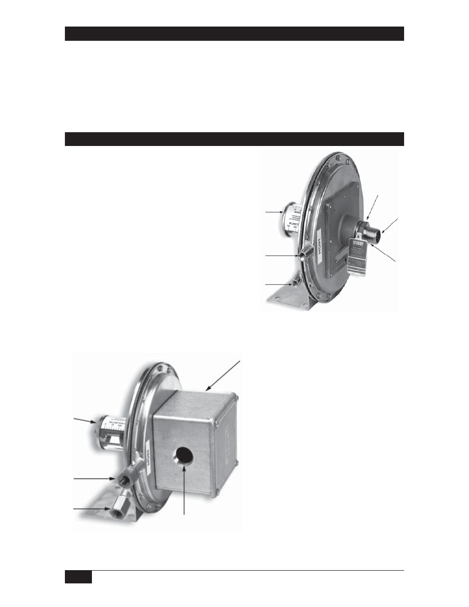
Process Connection
Hazardous Locations - 107EL
Non-Hazardous Locations - 107AL
The high-pressure side (marked HIGH) and the low pressure
side (marked LOW) have 1/8” NPT(F) process connections
unless 1/4” NPT(F) adapters were specified.
Set point adjustment screw (not shown)
High side process connection
Low side process connection
Hermetically sealed switching element capsule
18 AWG wire leads (not shown)
1/2” NPT(M) electrical conduit connection
3/4” NPT(F) electrcial conduit connection
Weatherproof switching element housing
Ensure that wiring conforms to
all applicable local and national
electrical codes and install unit(s)
according to relevant national and
local safety codes.
Safety Integrity Level (SIL) Installation Requirements
The SOR pressure switches have been evaluated as Type-A safety related hardware.
To meet the necessary installation requirements for the SIL system, the following
information must be utilized:
Proof Test Interval shall be one year.
Units may only be installed for use in Low Demand Mode.
Products have a HFT (Hardware Fault Tolerance) of 0, and were evaluated in a
1oo1 (one out of one) configuration.
Form 1538 (03.12) ©2012 SOR Inc.